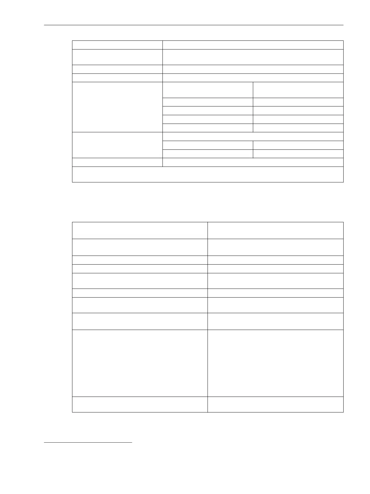
Rejection pulse charge > 200 µC
Current consumption, excited Approx. DC 1.2 mA to 2.0 mA (additionally to the current consumption
of the input impedance)
Power consumption, max. 1.5 W at DC 242 V
Pickup time Approx. 3 ms
Dropout time
29
Capacitive load (supply-line capaci-
tance)
Dropout time
< 5 nF < 3 ms
< 10 nF < 4 ms
< 50 nF < 5 ms
< 220 nF < 10 ms
Control voltage for the module
IO216
Range for 220 V control voltage
Threshold pickup 158 V to 170 V
Threshold dropout 132 V to 154 V
Maximum permitted voltage DC 300 V
The binary inputs contain interference suppression capacitors. To ensure EMC immunity, use the terminals
shown in the terminal diagrams/connection diagrams to connect the binary inputs to the common potential.
Relay Outputs
Standard Relay (Type S)
Making capacity
Max. 1000 W (L/R = 40 ms)
Max. 3600 VA (power factor ≤ 0.35, 50 Hz to 60 Hz)
Breaking capacity Max. 30 W (L/R = 40 ms)
Max. 360 VA (power factor ≤ 0.35, 50 Hz to 60 Hz)
AC and DC contact voltage 250 V
Permissible current per contact (continuous) 5 A
Permissible current per contact (switching on and
holding)
30 A for 1 s (make contact)
Short-time current across closed contact 250 A for 30 ms
Total permissible current for contacts connected to
common potential
5 A
Switching time OOT (Output Operating Time)
Additional delay of the output medium used
Make time: typical: 8 ms; maximum: 10 ms
Break time: typical: 2 ms; maximum: 5 ms
Max. rated data of the output contacts in accordance
with UL certification
DC 24 V, 5 A, General Purpose
DC 48 V, 0.8 A, General Purpose
DC 240 V, 0.1 A, General Purpose
AC 240 V, 5 A, General Purpose
AC 120 V, 1/6 hp
AC 250 V, 1/2 hp
B300
R300
Interference suppression capacitors across the
contacts
4.7 nF, ± 20 %, AC 250 V
11.1.4
29
For time-critical applications with low-active signals, consider the specified dropout times. If necessary, provide for active discharge
of the binary input (for example, a resistor in parallel to the binary input or using a change-over contact).
Technical Data
11.1 General Device Data
SIPROTEC 5, Low-Impedance Busbar Protection, Manual 905
C53000-G5040-C019-C, Edition 04.2021

 Loading...