PROFIBUS-DP - Parameterization in DIGSI
63
SIPROTEC PROFIBUS-DP - Communication profile
C53000-L1840-B001-03
4.1.4 Interface selection and mapping selection in DIGSI 4.3 or higher
When entering the device MLFB (order number) to create a new SIPROTEC device in
the DIGSI 4 Manager for parameterization, you are asked automatically for the
selection of PROFIBUS-DP as system interface if the SIPROTEC device has a
PROFIBUS-DP communication module at delivery.
Changing the system interface to PROFIBUS-DP for already existing devices in DIGSI
is also possible.
Protocol
assignment for
system interface
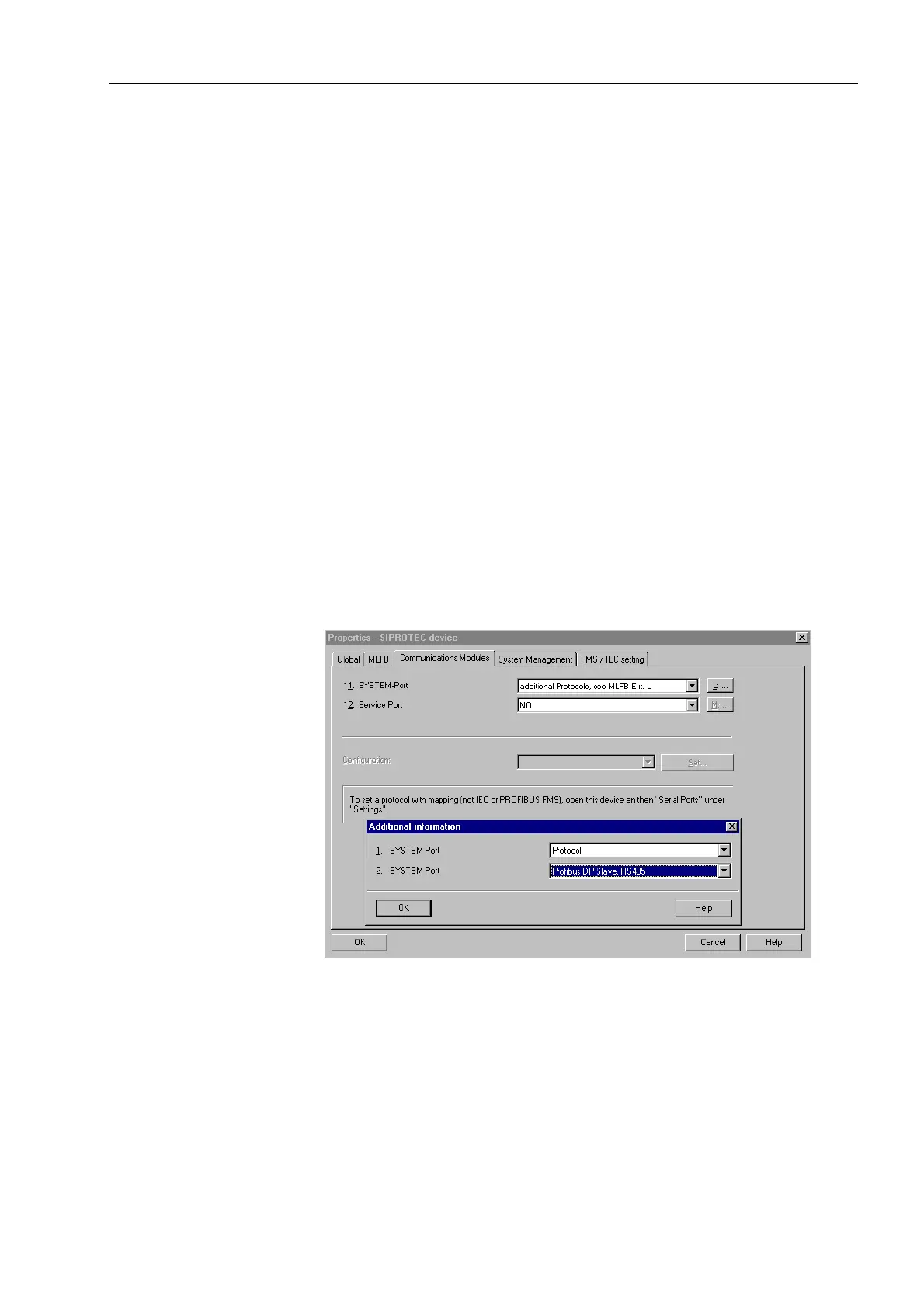
Select the SIPROTEC device in your project in the DIGSI 4 Manager and use
the menu item Edit - Object properties... to open the Properties -
SIPROTEC 4 device dialog window (ref. to Figure 4-3).
In the property sheet Communications Modules the entry “additional protocols,
see MLFB Ext. L” has to be selected for “11. SYSTEM-Port”.
By pressing the button “L: ...” the dialog window Additional information is
opened which is used to enter the type of the communication module.
Please select in the dialog window Additional information:
• “Protocol” or “none” (depending on the SIPROTEC device type) for
“1. SYSTEM-Port” and
• “Profibus DP Slave, RS485” or “Profibus DP Slave Fiber double loop ST” (depend-
ing on the hardware composition of the SIPROTEC device) for “2. SYSTEM-Port”.
Figure 4-3 DIGSI 4.3: PROFIBUS-DP protocol assignment
 Loading...


