Installation
5.1 Input side connection
Selectivity modules
44 Manual, 01.2017, C98130-A7579-A1-2-7629
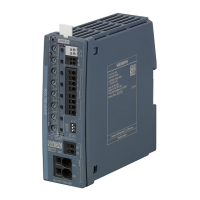
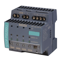
The power supply is connected using input terminal ① with the designation "24 V" and the
0 V terminal
② with the designation "0 V"; the "0 V" connection is not for the load supply, but
is only to supply the internal electronics of the selectivity module (terminal cross-sections,
see Chapter Figure 2-2 Terminal data (Page 13)).
The "0 V" connection is only used to supply the internal electronics of the selectivity
module. The 0 V of the connected loads must be routed directly to the power supply using
separate cables!
The input terminals of the selectivity module are designed for a maximum input current of
40 A. This must be taken into account when connecting several selectivity modules in
parallel using "loop through". If the total current demand of all selectivity modules
connected in parallel is more than 40 A, then the maximum current should be reduced to
40 A per branch by using additional feeder cables directly from the power supply to the
selectivity modules connected in parallel.
 Loading...
