T
Theresa OrtegaAug 25, 2025
What does it mean if my Siemens Transmitter says 'Pulse overflow'?
- XxbarberAug 26, 2025
A pulse overflow indicates that the actual flow is too big compared with pulse width and volume/pulse. Reduce the pulse width.
What does it mean if my Siemens Transmitter says 'Pulse overflow'?
A pulse overflow indicates that the actual flow is too big compared with pulse width and volume/pulse. Reduce the pulse width.
How do I fix 'Incorrect or no coil current' on Siemens SITRANS FM MAG 5000 Transmitter?
If there is incorrect or no coil current, check the cables and connections.
| Brand | Siemens |
|---|---|
| Model | SITRANS FM MAG 5000 |
| Category | Transmitter |
| Language | English |
Explains the manual's warning notice system and hazard grading.
Defines qualified personnel responsible for operating the device.
Notes on using Siemens products safely and correctly.
Lists registered and common trademarks used in the publication.
States consistency check and rights for technical changes.
Explains the manual's content, target audience, and principle of operation.
Lists previous document editions and their major changes.
Instructions for verifying delivery contents for damages and completeness.
Lists all components included in the product package.
Provides guidance on industrial security and cyber threat prevention.
Guidelines for ensuring product protection during transport and storage.
Clarifies that the manual does not modify warranty conditions.
Covers general installation requirements and instrument safety standards.
Specifies environmental conditions according to IEC 61010-1 for device operation.
Lists European directives (EMC, LVD, ATEX) the device conforms to.
Details conditions for safe use and Ex approvals for hazardous areas.
Lists specific requirements for electrical connections and installation in hazardous areas.
Lists the main components of the SITRANS F M MAG 5000/6000 flowmeter system.
Explains the flow measurement principle based on Faraday's law.
Lists sectors and industries where the flowmeters are suitable for use.
Describes key features such as power supply, dialog, and output modules.
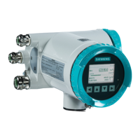
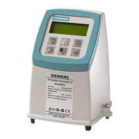
Details the different available versions of the MAG 5000 and MAG 6000 transmitters.
Explains how to read and interpret the information on the device's nameplate.
States suitability for indoor/outdoor installations and chapter scope.
Discusses factors affecting optimum flow measurement like orientation and vibrations.
Step-by-step guide for installing the compact version of the flowmeter.
Detailed instructions for mounting the transmitter and sensor in a remote configuration.
Information on installing the CT version, including calibration sealing.
Instructions on orienting the transmitter and keypad for optimal viewing.
Detailed wiring diagram and instructions for connecting power, outputs, and sensors.
Additional connection details for PTB K7.2 approved models.
Information on connecting add-on communication modules.
Instructions for commissioning the blind version using a standard transmitter.
Explains symbols and fields of the device's local user interface.
Outlines the structure of the operator and setup menus.
Step-by-step guide to change the password for setup menus.
Details parameters configurable in the basic settings menu.
How to customize visible menus in the operator menu.
Instructions for changing the transmitter's display language.
Explains configuration options for current, digital, and relay outputs.
Describes using external digital inputs for control and totalizer functions.
Details parameters for sensor configuration and calibration.
Explains how to reset totalizers or restore factory settings.
How to use service mode for checking outputs and logs.
Configuration settings specific to CT versions, including totalizers.
Information on adjusting excitation frequency for MAG 6000 SV.
Provides a checklist for verifying transmitter status and operation.
Contact information and resources for technical assistance.
Steps and forms for returning a device for service or repair.
Information on Siemens AG's recalibration service for sensors.
Explains the error system, acceptance levels, and error logging.
A comprehensive list of error codes, their meanings, and remedies.
Detailed technical specifications for MAG 5000/6000 flowmeters.
Presents accuracy figures and graphs based on flow velocity and conditions.
Details characteristics of current, frequency, pulse, and relay outputs.
Provides specifications for electrode and coil cables.
Outlines requirements for ambient temperature, capacitance, and cable glands.
Information on finding the latest ordering data for spare parts online.
Lists common spare parts and accessories with images.
Details the sun shield accessory.
Provides a high-level overview of the transmitter's menu structure.
Detailed diagrams of the basic settings menu options.
Diagrams illustrating reset mode options for totalizers and settings.
Diagrams for customizing the operator menu layout and displayed text.
Diagrams showing the process for changing the transmitter's password.
Table listing default factory settings for various parameters.
Table of Qmax values for different pipe diameters at 50 Hz.
Table of Qmax values for different pipe diameters at 60 Hz.
Tables specifying volume, pulse, and batch settings by dimension at 50 Hz.
Tables specifying volume, pulse, and batch settings by dimension at 60 Hz.
Information on accessing product documentation online and via mobile app.
Details on obtaining technical support through requests, online services, and representatives.