SITRANS TH/TR/TF
A5E32520693-01, 06/2013
23
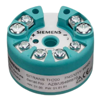
Nameplate structure (Page 5)
Auxiliary power supply electrical connection
Overview
Auxiliary power supply
Test connector for direct current measuring device
or connection for external display
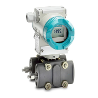
Example feed splitter for SITRANS TF with built-in
Shield support
Cable gland for auxiliary power supply/analog
Protective conductor connector
Connecting terminals "+" and "-"
Cable gland for sensor signal
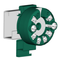
Figure 4-2 Auxiliary power supply electrical connection
1. Connect the wires for the auxiliary power supply ① to terminals "1"(+) and "2"(-) ④. Ensure that the polarity is correct.
The device is reverse polarity protected.
2. Connect the cable shield.
Connect the shield of the signal cables to the shield support
⑥. The shield support is electrically connected with the
housing.
 Loading...