Do you have a question about the Siemens SXG 75 and is the answer not in the manual?
Description of the RF section, including UMTS, GSM, Bluetooth transceivers, and receivers.
Visual representation of the RF section's components and interconnections.
Block diagram illustrating the baseband architecture and key components like MSM6250.
General features, block diagram, and specifications of the MSM6250 processor.
Explanation of clock generation and distribution for various system components.
Details on MSM6250 logic interface pad groups, their supplies, and voltage levels.
Summary of analogue signal functions for microphones, speakers, and sensors.
Table listing PM6650 voltage regulators, their output, and connected components.
Explanation of the PM6650 power-on and power-off sequence management.
Details the battery capacity, voltage, fuel gauge, and parameters.
Describes the two-stage shutdown process based on battery voltage levels.
Explanation of charging modes, control by PM6650, and temperature/voltage monitoring.
Details the SXG75 display module, its interface, and specifications.
Information on keypad assembly, key mapping, and interfacing with the MSM6250.
Detailed listing of accessory connector pins, their functions, and connections.
How USB signals multiplex with UART signals on the accessory connector.
Diagrams showing the location of key components on the bottom side of the main PCB.
| Status | Discontinued |
|---|---|
| SIM | Mini-SIM |
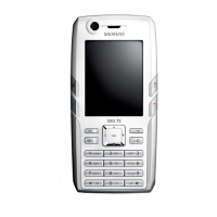
| Display Type | TFT, 256K colors |
| Display Size | 2.2 inches |
| Primary Camera | 1.3 MP |
| Alert types | Vibration; Downloadable polyphonic, MP3 ringtones |
| Loudspeaker | Yes |
| 3.5mm jack | No |
| WLAN | No |
| GPS | No |
| Messaging | SMS, MMS, Email, Instant Messaging |
| Browser | WAP 2.0/xHTML |
| Games | Yes + downloadable |
| Java | Yes, MIDP 2.0 |
| Stand-by | Up to 300 h |
| Colors | Black, Silver |
| Infrared port | No |
| Network | GSM 900 / 1800 / 1900 |
| Display Resolution | 240 x 320 pixels |
| External Memory | up to 1 GB |
| Phonebook | Yes |
| Bluetooth | 1.2 |
| USB | Yes |
| Features | MP3/AAC player, Organizer |