A5E32243983 The Probe – INSTRUCTION MANUAL Page 3
mmmmm
English
Interconnection
Cable Entry
System Diagram
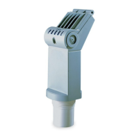
4” Sanitary Ferrule
119 mm (4.68")
97 mm (3.83")
dimensions
are approximate
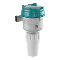
The Probe
clamp*
adjusting
wing nut
ferrule
tank
• mount The Probe onto the top of
the tank’s sanitary ferrule
• secure mating by surrounding
the joint with the clamp
• tighten adjusting wing nut
Note: Inside of sanitary
ferrule must be smooth, free of
burrs, seams or ridges.
*supplied with the Probe
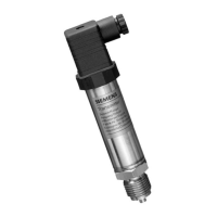
A.With lid closed, remove cable entry ’knock out’ on either side as required.
B.Open lid by loosening the lid screw.
C. Run cable to The Probe.
D.Connect loop wiring.
E. Close lid. Tighten screw to 1.1 to 1.7 N-m (10 to 15 in-lb) of torque
The Probe
loop
instrumentation