1
2
3
12
5
6
8
11
7
7
TPS- Installation Instructions for:
Lighting Panelboards P & P
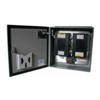
The following instructions are for the installation of the
Siemens TPS and L SPD modules in Siemens P and P
lighting panelboards (also for field replacement.)
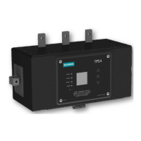
Figure : P Panel TPS Install
1
2
3
4
5
6
8
11
10
12
9
Item Description Qty. Torque
TPS
TPS Mounting Plate
#- Hex Screw with captive washer in-lb
#- Hex Thread Rolling Screw in-lb
Line Bus Connector * or
#/- Hex Screw w/captive washer * or in-lb
/- x ” Carriage Bolt
/- Believille Combo Nut
* or in-lb
Neutral Lug Wire Connection N/A in-lb
P Riser Bracket
a) P/P A-A = /- x /” Thread
forming screw
b) P A = /- x /” hex screw
with captive washer
* or See
Torque
Note**
” # AWG White Neutral Conductor
#- Hex Thread Rolling Screw in-lb
Figure : P Panel TPS Install
Table : Content for Installation in Lighting
Panelboards P, P
Step ) Lock off all power supplying this equipment before
working on it.
Step ) Remove the trim and dead front (and any previously
installed TPS or TPS unit.)
Step ) Attach TPS Mounting Plates (Item , Places) to
TPS using - SEM screws with captive lock washer
(Item ). The mounting plates should be attached to the
TPS with the offset oriented towards the top of the unit.
Torque Screws to values listed.
Step ) P Panel Install Only: Attach P Riser Brackets to
TPS Mounting Plates using - Thread Forming Screws
(Item ). Use inside set of mounting slots on Mounting Plates.
Step ) Install Line Bus Connectors (Item , places) on
TPS using /- SEM screws with captive lock washer
(Item ). Tighten but do not torque to allow Bus Connector
angle adjustment.
Step ) Position the TPS unit on the panel base rail so
that the TPS Line Bus Connectors line up with panel bus
mounting toles. Slide the unit toward the interior until
the four mounting holes line up with the four holes in
the base rail.
Step ) P Panel: Fasten unit to the main bus using the
P Panel Carriage Bolt and Nut with captive washer
(Item ) provided w/ P Panel. Do not Torque at this time.
Attach the Mounting Plates (item ) to the base rail using
- hex thread forming screws (item ) provided as
shown in Figure .
Step ) P Panel: Fasten unit to the main bus using the P
Panel Bus Bolt. (Item ) provided w/ P Panel. Do not Torque
at this time Attach the P Riser Brackets (item ) to the base
rail using - hex Thread Rolling screws (item ) provided
as shown in Figure #.
Step ) If present, connect TPS Neutral Connection Lug
(item ) to Panel Neutral using AWG minimum wire
(item ). For best SPD performance, trim wire as required
to provide shortest possible route between TPS Neutral
connection and Panel Neutral Connection. Route wire as
straight as possible and use gentle radius on any bends.
Do not kink wire. Prevent wire from encroaching breaker
locations.
Step ) Torque all connections to the values as specified
in Table or on appropriate panel label.
Step ) Replace dead front supports (if they had been
removed for ease of placing the SPD) by installing screws,
finger tight. Then tighten with tool. Replace trim and
dead front.
Factory assembled TPS and TPS SPD units will use
appropriate Screws or Bolt/Nut combinations depending on
the panel configuration for attachment to the bus. When
replacing SPD units in the field, re-use the hardware originally
installed and use the table as a guide for proper torque values.
NOTE: For wired installations, see details in the previous section.
* only 2 tabs for single phase modules
** Torque Note: For Item 10, see Bus Connection Tightening Torque
values on label 15-A-1043-01 inside panel board.
TPS- Surge Protection Device | Installation Guide / User Manual
 Loading...