TPS- Installation Instructions for:
Display Rotation
The following instructions are for rotating the display
assembly in the Siemens TPS and L SPD modules. The
display may be rotated if care is taken to not unduly crimp/
damage the ribbon cable that feeds the display. If the display
is mounted in an orientation other than what is needed, care
must be taken to note orientation of Phase A and Phase C
buses as the TPS’s power monitoring features may report
the phases as reversed.
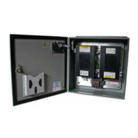
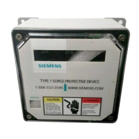
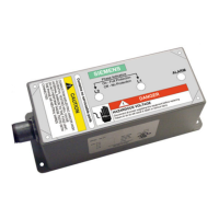
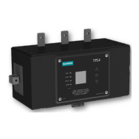
Figure : Display unit on TPS and L
Remove the - Tamper Resistant screws in the corner of the
display using a T Tamper Resistant Torx bit. Retain screws.
Rotate display pocket degrees. Carefully fold ribbon cable
below pocket and route to minimize sharp bends and double
over cable directly beneath the display pocket.
Reinstall retained - tamper resistant screws and torque
screws to value listed.
Table : Content for display rotation
1
2
Item Description Qty. Torque
TPS Display (re-use)
#- T Tamper Res Screws (re-use) in/lbs
NOTE: While the TPS4 SPD can be used in Busway (Busplug) and Motor
Control Center (MCC) applications, installation instructions are omitted
from this manual because the SPD is ONLY factory installed for these
applications. Field replacement is not possible for Busway and MCC
applications.
Installation Guide / User Manual | TPS- Surge Protection Device
 Loading...