➋
CONTINUE HERE
This positive power source
MUST BE SWITCHED, and
must be protected with a fuse);
b) the light switch (also after the
fuse in the fuse box); and
c) a good ground location .
2. Connect the positive (+) and nega-
tive [ground] () wires as shown in Dia-
gram C.
3. Connect the appropriate positive (+)
and ground (negative []) wires to the ter-
minals on the Voltmeters lamp socket. Be
sure that the ground wire from the lamp
socket uses its own ground connection
(separate from the one used by the gauge
terminal ground), as shown in Diagram C.
PD[ PP
PP
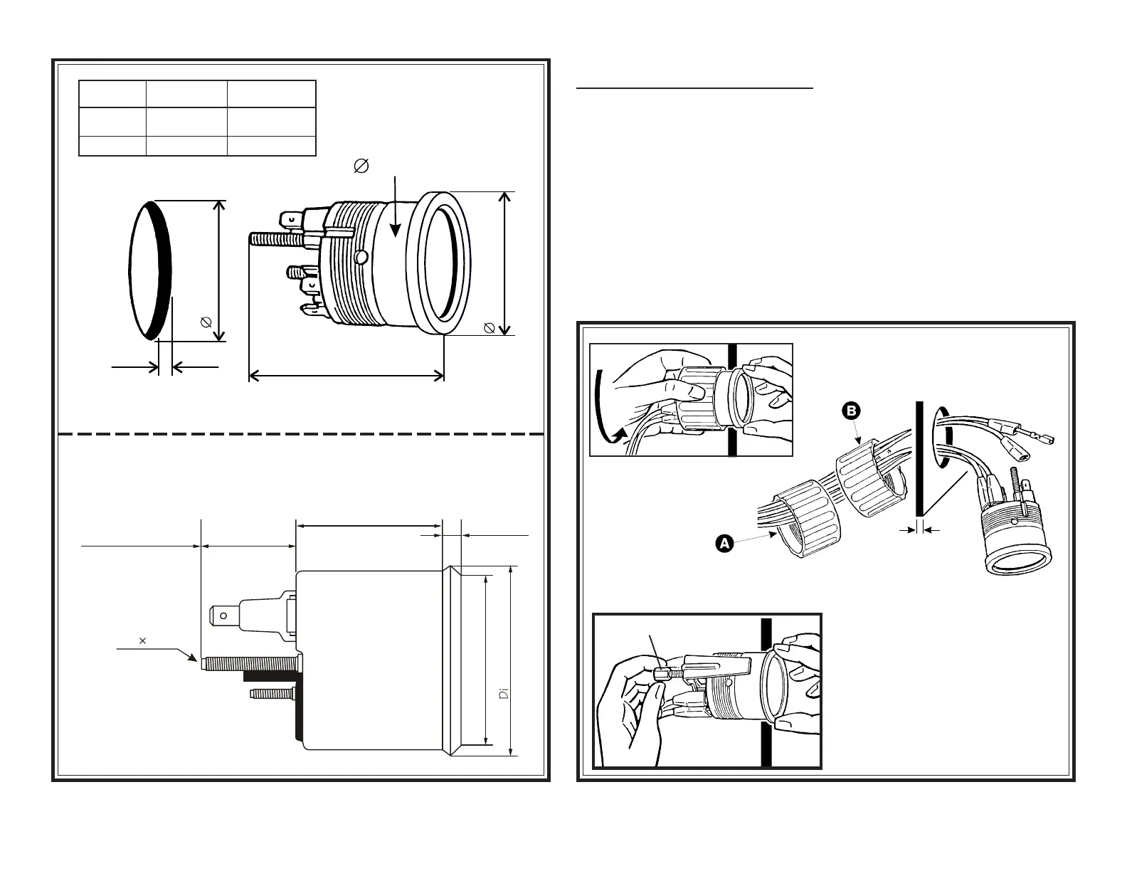
'LPHQVLRQ ¬$
'LPHQVLRQ ¬%
'LPHQVLRQ ¬$
Diagram A
Gauge dimensions
!'
$#]]
4Y]U^cY_^²1³
((""#]]
!'&
$$']]
"=$
ð
4Y]U^cY_^²2³
Pro-Cockpit, Industrial and Series 1 Gauges
Table 1
Gauge
Pro-Cockpit:
All other:
Dimension
“A”
2 ⁵⁄₈" (66 mm)
2 ¹⁄₁₆" (52 mm)
Dimension
“B”
2.77" (70 mm)
2.19" (55.6 mm)
Diagram B
Mounting using VDO Mounting Bracket or VDO Spin-Lok
ä
Clamp
DO NOT OVERTIGHTEN!
At this point, the installation and wiring
of the your new VDO Voltmeter is com-
plete. Turn on the ignition and the lights
in the car and check to see that the
imstrument and light are working prop-
erly. If they arent, re-check your wiring,
referring to the wiring description in Dia-
gram C.
Mounting Nut direction
depends on panel width
A: 0 .4" (0 10 mm)
B: .4" .8" (10 20 mm)
TOP:
VDOs Spin-Lok
ä
Mounting Clamp
é
LEFT:
VDO Mounting Bracket
ç