6/8
Building Technologies Electronic Heat Meter CE1N5331en
HVAC Products 03.11.2005
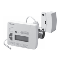
Determination of pressure loss
∆
0,5
0,4
0,3
0,2
0,1
0,05
0,04
0,03
0,02
0,01
1,0
0,2
0,3
0,4 0,5
1,0
1,5
2
3
4
5
Q
p
5333D01
0,6 1,2
2,5
6
Q
p
0,6 m
3
/h
Q
p
2,5 m
3
/h
Q
p
1,5 m
3
/h
Pressure loss curve
∆p Pressure loss in bar
Q Flow in m
3
/h
Mounting instructions
• Observe the local regulations for the use of heat meters (mounting, sealing, opera-
tion, etc.).
• Mount the heat meter according to the type either in the flow or return between two
shut-off valves. It must be easily accessible for reading and service work.
• A stilling channel is required at the inlet in front of the device:
− 150 mm for installation lengths of 80 mm and 110 mm
− 200 mm for an installation length of 130 mm
• If the device is only to be used when starting up, the spacer can be mounted first.
• Before installing the meter, rinse the pipe well; mount the spacer for this purpose.
• When installing, observe the flow sign – an arrow on the flow meter.
• If tees of a different brand are used, ensure that they comply with the standard
EN1434!
• Position the calculator so that the display is easy to read.
• After mounting, test the system for pressure.
• Protect the calculator, both temperature sensors and the screw pipe connections
with seals against unauthorized access.
• Insulate the lead at the installation site of the temperature sensors.
Operating hint
• Observe the local regulations for recalibration purposes.

 Loading...