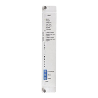
A6V101055479_en--_a
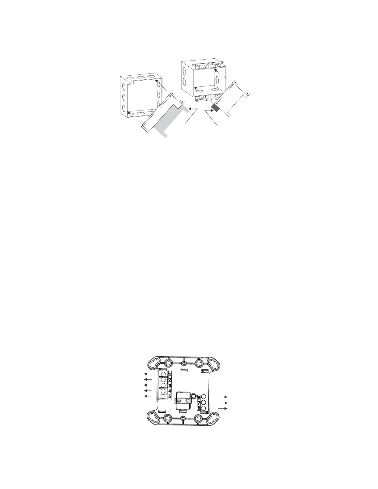
BARRIER
4-INCH SQUARE BOX
2 1/8-INCHES DEEP
BREAK OFF THIS
SECTION WHEN
USING A 4-INCH
SQUARE BOX
2
.0 i
n
5.
0
6
in
1
.
1
8
7
i
n
DOUBLE GANG BOX
3 1/2-INCHES DEEP
BREAK OFF THIS
SECTION WHEN
USING A DOUBLE
GANG BOX
3
.
25
in
4
.5
i
n
Figure 6
Installing the XTRI-R Control Module Barrier
WIRING ENTERING OUTLET BOX
All power limited wiring must enter the outlet box separately from the electric light, power, Class 1, or
non-powered limited fire protection signaling conductors. For the XTRI-R, wiring to terminal block
positions 1, 2, 3, 4, and 5 must enter the outlet box separately from terminals 6, 7, and 8.
NOTE: Minimize the length of wire entering the outlet box.
WIRING AT THE TERMINAL BLOCKS
Power Limited Wiring: (Refer to Figure 7) Wiring to positions 1, 2, 3, 4, and 5 is power limited.
Non-Power Limited Wiring: Wiring to positions 6, 7, and 8 is considered non-power limited.
CAUTION: Ground shield of device line ONLY at the specified location on the Control Panel. Non-
shield cable can be used for Input.
CAUTION: EOL device must be a 470 ohm, 1% 1/2W resistor for wire open supervision, which comes
with the product.
P
N
N
N
P
P
P
P
P = POWER LIMITED
N = NON-POWER LIMITED
WIRES CONNECTED TO TERMINALS
1 THROUGH 5 TO ENTER/EXIT
ELECTRICAL BOX OPPOSITE SIDE
FROM WIRES CONNECTED TO
TERMINALS 6 THROUGH 8.
Figure 7
XTRI-R Power Limited Wiring