A6V101055479_en--_a
NOTES:
1. All supervised switches must be held closed and/or open for at least a quarter of a second to guarantee
detection.
2. End of line device: 470 ohm, 1% 1/2W resistor, P/N A5Q00073045, and use Model TB-EOL with 470 ohm, 1% 1/2W
resistor.
3. For polarity insensitive wiring, Line 1 and Line 2 can be either line of the device loop.
4. Supervised switch ratings:
Voltage maximum: 27 VDC
Current maximum: 6mA during polling
Contact resistance maximum: 10 ohms
Maximum cable length: 200 feet (18 AWG)
C
Line to line
: 0.02uF
Max line size: 14 AWG
C
Line to shield
: 0.04uF
Max line size: 14 AWG
Min line size: 18 AWG
5. Relay contact ratings:
4A, 125 VAC resistive
4A, 30 VDC resistive
Inductive:
3.5A, 120 VAC (0.6 P.F.)
3.0A, 30 VDC (0.6 P.F.)
2.0A, 120 VAC (0.4 P.F.)
2.0A, 120 VAC (0.35 P.F.)
2.0A, 30 VDC (0.35 P.F.)
The relay is shown in standby condition.
6. In the device line, up to 30 of any compatible devices in polarity insensitive mode with 20 ohms max line resistance
can be isolated between two modules in isolator mode in a Class A Style 6 wiring.
7. In the device line, up to 30 of any compatible devices in polarity insensitive mode with 20 ohms max line resistance
can be isolated behind one module in isolator mode in a Class B Style 4 wiring.
8. HLIM isolator module and SBGA-34 sounder base cannot be used in the same loop with the modules in isolator
mode.
1
5
4
3
2
6
7
8
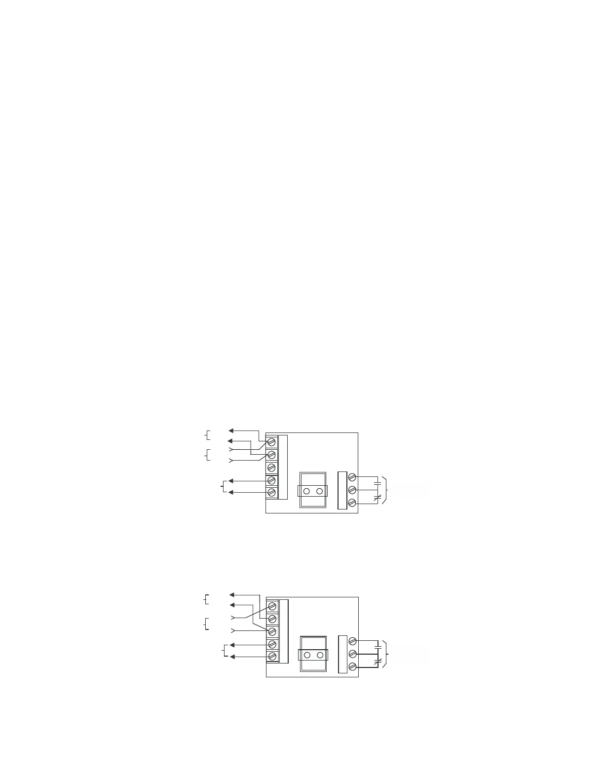
Programmable
Relay Contacts
See Note 5
To monitored
switches, refer to
Fig. 3 and 4
Line 1
Line 2
Line 1
Line 2
To next
addressable device
From control panel
or previous
addressable device
Figure 8
XTRI-R Polarity Insensitive Mode Wiring
1
5
4
3
2
6
7
8
Programmable
Relay Contacts
See Note 5
To monitored
switches, refer to
Fig. 3 and 4
Line +
To next
addressable device
From control panel
or previous
addressable device
Line -
Line +
Line -
Figure 9
XTRI-R Isolator Mode Wiring