12
This screen allows the selection of several engineering units. With the cursor on the default
value as shown, press the ↑ ↓ buttons to select between:
FEET NTU
INCHES PPM
GPM DEG. F
PSI DEG C
LPM FLOATS
ING HG
MGD
Use the ↑ ↓ buttons to select the desired engineering units then with the → ← buttons,
highlight ‘NEXT’ and press ‘ENTER’ to access the “DISPLAY FILTER” screen.
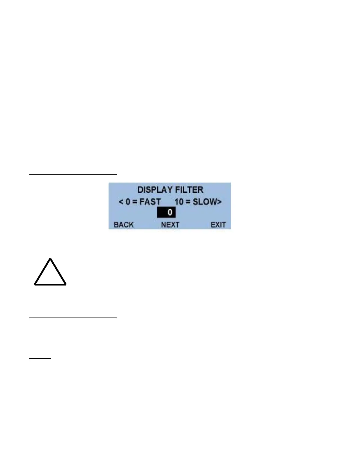
DISPLAY FILTER SCREEN
Use the ↑ ↓ buttons to change the amount of filtering applied to the input signal. ‘0’ is no filter
and ‘10’ is high filter.
Too much filtering will dampen process responses.
Scroll to ‘NEXT’ and press ‘ENTER’ to return to the Menu 2.
ANALOG OUTPUT (AOUT)
Use the → ← keys to highlight the ‘AOUT’ item and press ‘ENTER’ to access the analog output
signal settings.
NOTE: There are four analog outputs on the DPC: AOUTPUT 1 and AOUTPUT 2 are
speed vs. level setpoints which are only utilized on variable speed drive applications.
This screen allows the user to program the speed of the drive at a selected level. Both
level and drive speed are selectable.
!