25
AO
Raw output at speed output #1 (AOI)
DIGITAL
DIGITAL INPUT
1 Pump 1 Run Feedback 1DI
2 Pump 2 Run Feedback 2DI
3 Critical Alarm Pump 1 3DI
4 Critical Alarm Pump 2 4DI
1 Pump 1 HOA in Auto 1AI
2 Pump 2 HOA in Auto 2AI
3 Seal Leak Pump 1 & 2 3AI (see SETUP for other options)
DIGITAL OUTPUT
1 Relay 1 Run to Pump 1 RLY1
2 Relay 2 Run to Pump 2 RLY2
3 Level Alarm RLY3 (see SETUP for other options)
4 General Alarm RLY4
1 Sensor Fail DO1 (see SETUP for other options)
2 Pump 1 Fault DO2
3 Pump 2 Fault DO3
4 Seal Leak P1 or P2 DO4 (see SETUP for other options)
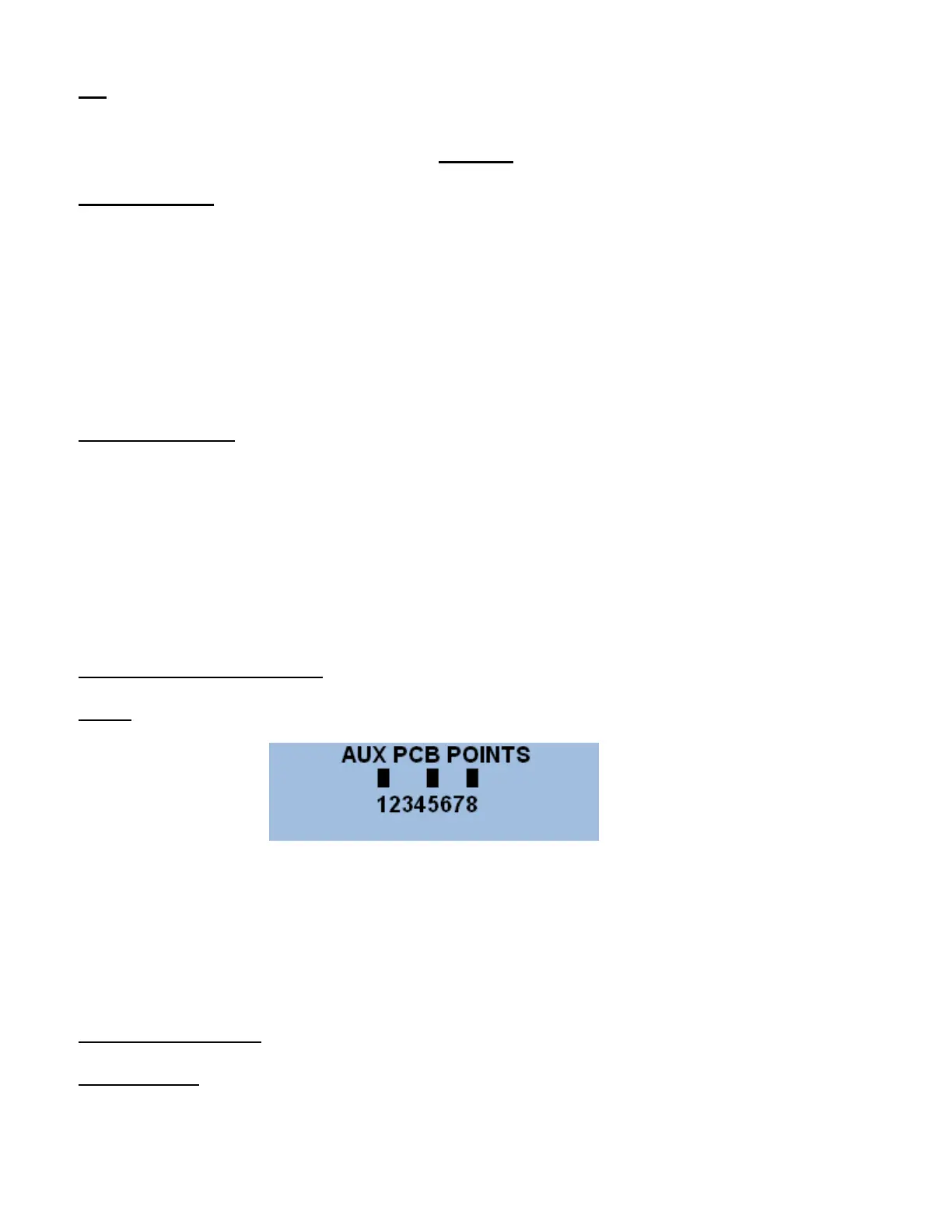
AUX DIAGNOSTIC SCREEN
Note; each point can be assigned as an input or an output. See drawing.
This screen will follow the original Diag Screen when the aux PCB is enabled. It shows when a
point is sinked to ground. This is either by the output sinking a relay or the common being
applied as an input.
Press ENTER to exit to main menu.
NOTES ON ALARMS
General Alarm output is energized for any alarm in the system that becomes active.