CSTO 082 C-DIAS SAFETY-DIGITAL OUTPUT MODULE
Page 24 31.01.2018
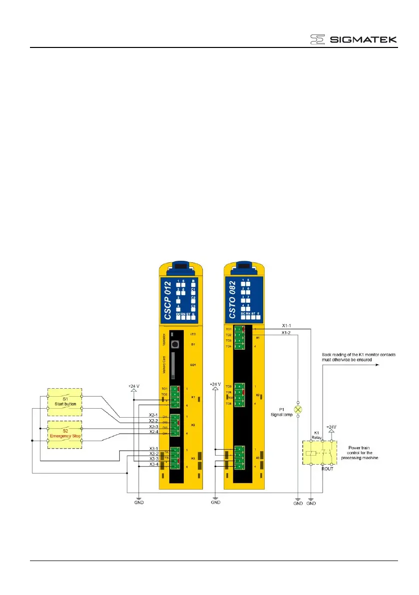
Implementation
• For switch S1, the start button and S2, the Emergency Stop switch, 2 safe in-
puts are required for each.
• Two safe outputs are needed for control of the relay K1 and the signal lamp P1.
• The normally open contacts of the start button S1 are connected to the signal
outputs A and B over 2 channels (cross-circuit detection) and wired to 2 safe
inputs.
• The normally closed contacts of the Emergency Stop switch S2, are connected
to the signal outputs A and B over 2 channels (cross-circuit detection) and wired
to 2 safe inputs.
• The monitor contact of the K1 relay switch is otherwise read back.
The following block diagram shows the implementation of the circuit with help from a CSTO
082 Safety output module, a CSCP 012 Safety CPU and the previously mentioned external
components. Here, it is assumed that the both modules are mounted on a correctly in-
stalled C-DIAS module carrier.
Fig. 11: Example structure diagram
 Loading...