C-DIAS SAFETY DIGITAL OUTPUT MODULE CSTO 082
1.5 Page 3
Connector Plug Coding ..................................................................................... 19
Error Response .................................................................................................. 20
Restart Errors ............................................................................................................. 20
Troubleshooting .......................................................................................................... 21
Troubleshooting with the SafetyDesigner ................................................................... 21
Correcting a wiring error ............................................................................................. 21
Output Circuit ..................................................................................................... 22
Practical Example of a Circuit ........................................................................... 23
Requirements ............................................................................................................. 23
Implementation ........................................................................................................... 24
Connection Diagram ................................................................................................... 25
List of Illustrations
Fig. 1: Example of a minimum system for a safety-related control ......................................... 6
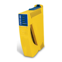
Fig. 2: CSTO 082 .................................................................................................................... 8
Fig. 3: Mechanical dimensions ............................................................................................. 10
Fig. 4: Inductive load ............................................................................................................ 12
Fig. 5: Capacitive load .......................................................................................................... 12
Fig. 6: CSTO 082 circuit ....................................................................................................... 16
Fig. 7: Connector plug coding............................................................................................... 19
Fig. 8: Simplified status diagram .......................................................................................... 20
Fig. 9: Output circuit structure .............................................................................................. 22
Fig. 10: Simplified representation of the processing machine .............................................. 23
Fig. 11: Example structure diagram ...................................................................................... 24
List of Tables
Table 1: C-DIAS bus connector layout ................................................................................... 6
Table 2: Input specifications ................................................................................................. 11
Table 3: Allowable output loads ............................................................................................ 12
Table 4: Electrical requirements ........................................................................................... 13
Table 5: Safety parameters .................................................................................................. 14
Table 6: Environmental conditions ....................................................................................... 15
Table 7: Miscellaneous ......................................................................................................... 15
Table 8: LED Display ............................................................................................................ 17
Table 9: Connector layout .................................................................................................... 18
Table 10: Connection diagram example ............................................................................... 25
 Loading...