AP05
Installation Deutsch
AP05 · Datum 25.09.2018 · Art. Nr. 88847 · Änd. Stand 316/18
10
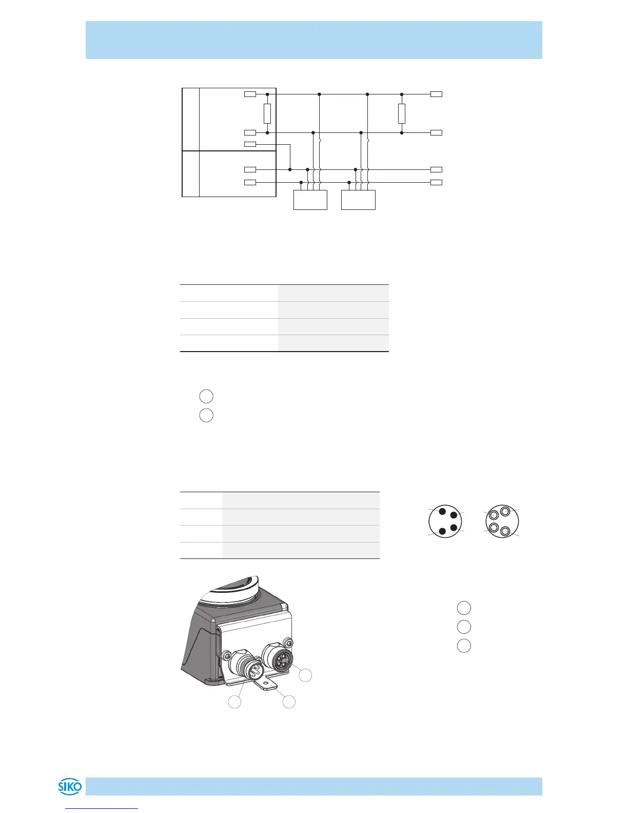
Abb. 5: Anschlussschema CAN
24 V
24 V
CAN_GND
CANL
CANH
120 R
CANH
CANL
Node 1
120 R
Node n
0 V
0 V
Bus-Master
Versorgung
Datenübertragung Schnittstelle CAN
CAN Baudrate max. Busnetzlänge
125kbit/s 320m
250bit/s 160m
500bit/s 80m
1Mbit/s 40m
Anschlussbelegung
•
1
Bus EIN: Stift 4 pol. M8 (siehe Abb. 6).
•
2
Bus AUS: Buchse 4 pol. M8 (siehe Abb. 6).
Zubehör Kabelverlängerungen, Gegenstecker und BUS-Abschlusswider-
stand siehe Kapitel 8.
PIN Belegung
1 DÜB/CANL
2 DÜA/CANH
3 +UB
4 GND
1
Bus EIN
2
Bus AUS
3
PE Anschluss
2
31
Abb. 6: Anschlussbelegung
Litzenquerschnitt Leitungen 0.14 ... 0.5mm².
 Loading...