1 2 MA503 Datum 08.01.2001 Art.Nr. 79539 Z.Nr. 8664078 Änd.Stand 2/01
• Fix cover strip (both ends should slightly
overlap).
• Also fix cover strip’s ends to avoid unin-
tentional peeling.
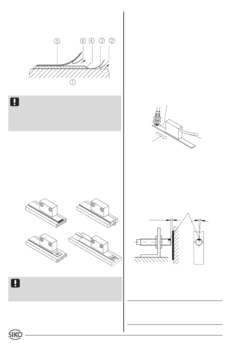
Fig. 1: Mounting of the magnetic strip
Attention ! Do not expose the system to magne-
tic fields. Any direct contact of the magnetic
strip with magnetic fields (eg. adhesive magnets
or other permanent magnets) is to be avoided.
Sensor movements during power loss are not
captured by the follower electronics.
Mounting examples
Mounting with chamfered ends (fig. 2) is not
recommended unless the strip is installed in a
safe and protected place without environmental
influences. In less protected mounting places
the strip may peel. There we recommend moun-
ting accord. to fig. 3 and 4.
Mounting in a groove (fig. 5) best protects the
magnetic strip. The groove should be deep
enough to totally embed the magnetic strip.
Fig. 2 Fig. 3
Fig. 4 Fig. 5
3.2 Mounting the sensor
Attention ! MA503 with socket connector for
sensors Type A, B, F or L to be combined with
magnetic tape MB or MB5. Please also read User
Instructions supplied with magnetic sensors.
Use two M3 screws to fix the magnetic sensor
A via the ø3.5 mm through holes.
Use two M2.5 screws to fix the magnetic sensor
B via the two threaded holes.
Magnetic sensor F can for example be mounted
by using a mounting bracket. For fixing sensor to
mounting bracket use bores and the two nuts
M8x0.5.
Use two M3 screws to fix the magnetic sensor
L via the ø 3.2 mm through holes.
• Cable layout should avoid damages due to
cable strain or other machine parts. If necessary
use a drag chain or protective hose and provide
for strain relief.
• Sensor must be aligned correctly with
respect to the counting direction (see fig. 6).
1
Precondition: Parameter 'Counting direction' (_dir_) in pro-
gramming mode must be programmed to "dn",
Fig. 6: Definition of counting direction / mounting
• When mounting the magnetic sensor, ensure
that the gap between strip and sensor and the
max. admissable deviation are maintained over
the total measuring length! (see fig. 7 and 8)
Fig. 7: Mounting of sensor Typ F
The gap between sensor and magnetic strip
should according to the following table.
type of display gap
EG10 0.1 ... 2 mm
TF 0.1 ... 2 mm
TS 0.1 ... 2 mm
Tab. 1: gap between sensor and magnetic strip
counting
direction
positive
1
travel direction
sensor
cable outlet
red marking
Signal
B before A
Sensor A,B or L
Sensor F
0.1 ... 2mm
<3°
red marking