MA503 Datum 08.01.2001 Art.Nr. 79539 Z.Nr. 8664078 Änd.Stand 2/01 1 3
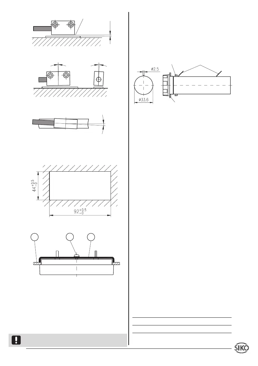
Fig. 8: Mounting of sensor
3.3 Mounting the display
Below are the dimensions for panel mounting:
Fig. 9: Panel mounting
Fig. 10: Mounting EG10
EG10 : Push device into panel (3). Tighten
bracket screw on the rear (2). Align device on
front plate and tighten screw.
Bench housing TF and TS
The rubber feet can be removed to enable the
unit to be screwed down.
Attention ! Max. reach of screw is 5.0 mm!
3.4 Mounting of the battery box for EG10
The battery box supplied together with the dis-
play are for panel mounting. The battery box
should be mounted at a ‘cold’ site: heat accele-
rates the self-discharge of batteries.
Below are the dimensions for panel mounting:
Fig. 11: Battery box for operating voltage 7
(3Volt , 2xBaby/R14)
4. Electrical connection
• Wiring must only be carried out with power off!
• Provide standed wires with ferrules.
• Check all lines and connections before swit-
ching on the equipment.
Interference and distortion
All connections are protected against the effects
of interference. The location should be selec-
ted to ensure that no capacitive or inductive
interferences can affect the sensor or the
connection lines! Interference can be caused
by motors, switch gear, cyclic controls and
contactors. Suitable wiring layout and choice of
cable can minimise the effects of interference.
The sensor should be positioned well away from
cables with interference; if necessary a protec-
tive screen or metal housing must be provi-
ded. The running of wiring parallel to the mains
supply should be avoided.
Power supply
The unit is battery-powered. EG10 version has
external power supply through connection cable
and enclosed battery box. TF and TS casing is
with integral battery box.
U
B
= 3 VDC (operating voltage 7 for TF+TS or EG10)
Designation Color(only for EG10)
+ U
B
red
GND black
Cut-out in control panel
3 1
2
panel:
thickness max. 3,2mm
nut
flat connector 2,8x0,5mm
cable length max. 2,0m
Max. deviation
< 1°
< 3°
< 3°
active side
Attention ! Gap
according to Tab.1