1 4 MA503 Datum 08.01.2001 Art.Nr. 79539 Z.Nr. 8664078 Änd.Stand 2/01
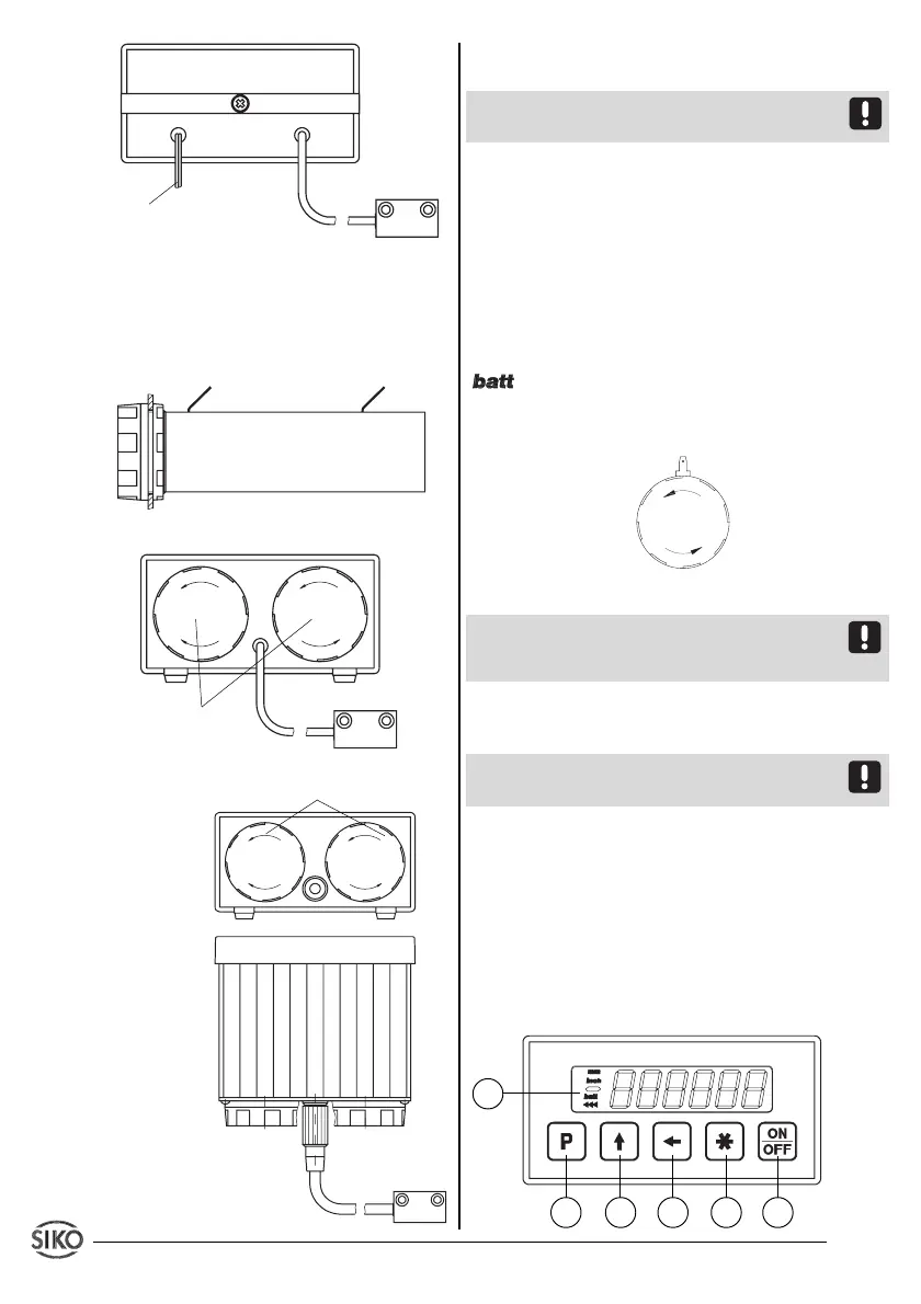
battery box
Sensor
Fig. 12: Built-in housing EG10
Connection of the battery box (only for EG10)
The battery box (mounted as described in chap-
ter 3.4) has to be connected as follows:
Fig. 13: Connection of the battery box
Fig. 14: Bench housing TF
Fig. 15: Bench housing TS
cable for power supply
Sensor
Display and sensor form one unit and must not be
interchanged when used with bench casing TS.
Bench casing's and connector's device number
must be identical.
Battery types
Batteries are not supplied together with the
MA503. The following standard types could be
used:
for
operating voltage 7 (3Volt)
:
2 x Baby / R14
Change of batteries
When display shows blinking 'low-batt symbol'
batteries should be exchanged as soon as
possible.
Unscrew cap to insert / remove batteries.
Fig. 16: Change of batteries
When exchanging the batteries take care that
their polarity is correct ! Take the marking on the
bottom of the box as orientation.
Sensor connection (if necessary)
via 7-poles rear side socket.
Attention! No modifiction of the sensor connec-
tion, eg. by cable extension, is permitted.
5. Commissioning
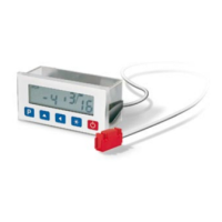
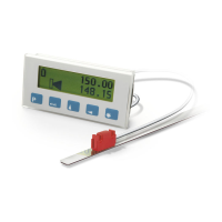
Five membrane keys on the front panel are used
for programming and operation of the display.
Keys’ function
Depending on the operating mode the keys may
have additional functions (see 'Programming
mode' and 'Input mode'). The keys are pressed
singly or in pairs (two together).
operating volta-
ge 7 (3Volt)
1
2
3
4 5
6
operating voltage 7 (3Volt)
+U
B
GND
battery box
Sensor