RV-C OmniScope Manual
Universal Diagnostic Module
The Universal Diagnostic Module can be used to
troubleshoot any RV-C device, regardless of the
make or manufacturer. All devices that are fully
RV-C compliant provide basic troubleshooting
information that this module can display and
interpret.
It is important to select the proper target device
before starting this program. The module will
provide information only for the selected device.
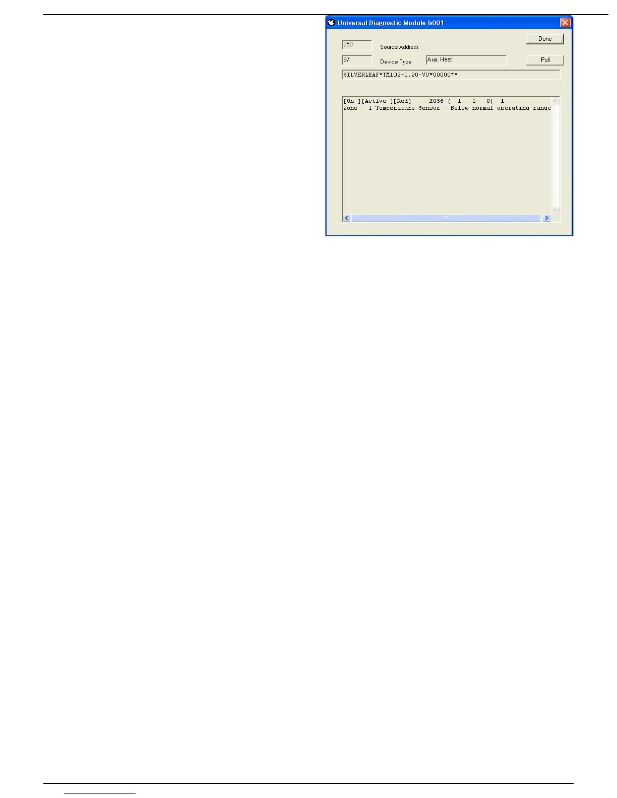
The module displays the Source Address for the
target device, along with the Device Type (or
DSA). The Device Type indicates generally what
type of product the module is looking at. Note that
sometimes a product may include several different
devices. For example, a generator may include a
“Generator” (DSA 64) and a “Genstart Controller” (DSA 65). One of these devices may be
malfunctioning while the other is functioning fine. Or, one may have a problem linked to the other.
The module also displays the full Product Identification. This is a long string of letters and
numbers separated by asterisks, and indicates the manufacturer, product model, and may include
serial numbers as well. The details are up to each manufacturer.
The main window shows the diagnostic information, as provided by the device in the DM1
diagnostic message. The first three values, shown in brackets, shows the general status of the
device. First, whether the device is On or Off. Second, whether it is Active or Inactive. Third,
whether the device is in a “Yellow” or a “Red” fault condition.
The distinction between On/Off and Active/Inactive varies among devices, but most devices are
either Off, On and Inactive, or On and Active. On and Active means it is fulfilling its designed
purpose at this moment. On and Inactive means it is not producing anything at the moment, but it
is prepared to do so at any appropriate moment - it is “standing by”. And Off means it will not do
anything without some intervention (usually, but not always, from the user). Note that an item that
is Off likely still has power - otherwise it couldn't tell the network that it was off.
Generally “Yellow” faults are situations which can be remedied with only basic intervention, or
have negligible effect on the operation of the device. A typical “Yellow” fault is low battery levels
for an inverter. “Red” conditions are more serious, and generally require attention from a
technician. These guidelines are subjective, of course, and manufacturers may interpret them
differently.
The next item displayed is a number called the SPN, or “Suspect Parameter”. This number has
two different forms, and the module shows both forms. In the raw form the SPN is just a number -
in the example above it is 2056. In the parsed form it is a series of three numbers - in the example
those numbers are 1, 1, and 0.
The interpretation of these numbers depends on the product. Most manufacturers provide a
table of the SPNs for their device, and that table will indicate the proper form for that device. The
distinction relies on whether the device is designed to allow multiple “instances” on the network.
The parsed form allows the table to show which specific device the fault applies to. The raw form
is used for products that can't have more than one installation on the RV.
Regardless of the form, the purpose of the SPN is the same. It identifies what component of the
device is malfunctioning. For example, in a generator the SPN might refer to the oil pressure or
tachometer. In a slide room the same SPN might refer to a proximity switch. Every different
device has its own list of potential SPNs.
The last number (1, in our example), is the Failure Mode, or FMI. This number is universal
Page 10 10/31/17