RV-C OmniScope Manual
Introduction to RV-C
The network or 'Can Bus' for RVs is called RV-C. It's a standard for RV appliances to talk to
share information, provide diagnostic data, control and be controlled. It is a “peer” network,
meaning every appliance (black box/ display), or “node”, is equal in the eyes of the network. A
typical network will consist of at least one or two control panels, one multipurpose controller, and
any number of appliances such as inverters, generators, and slide rooms. All the data is shared
digitally using a single pair of wires.
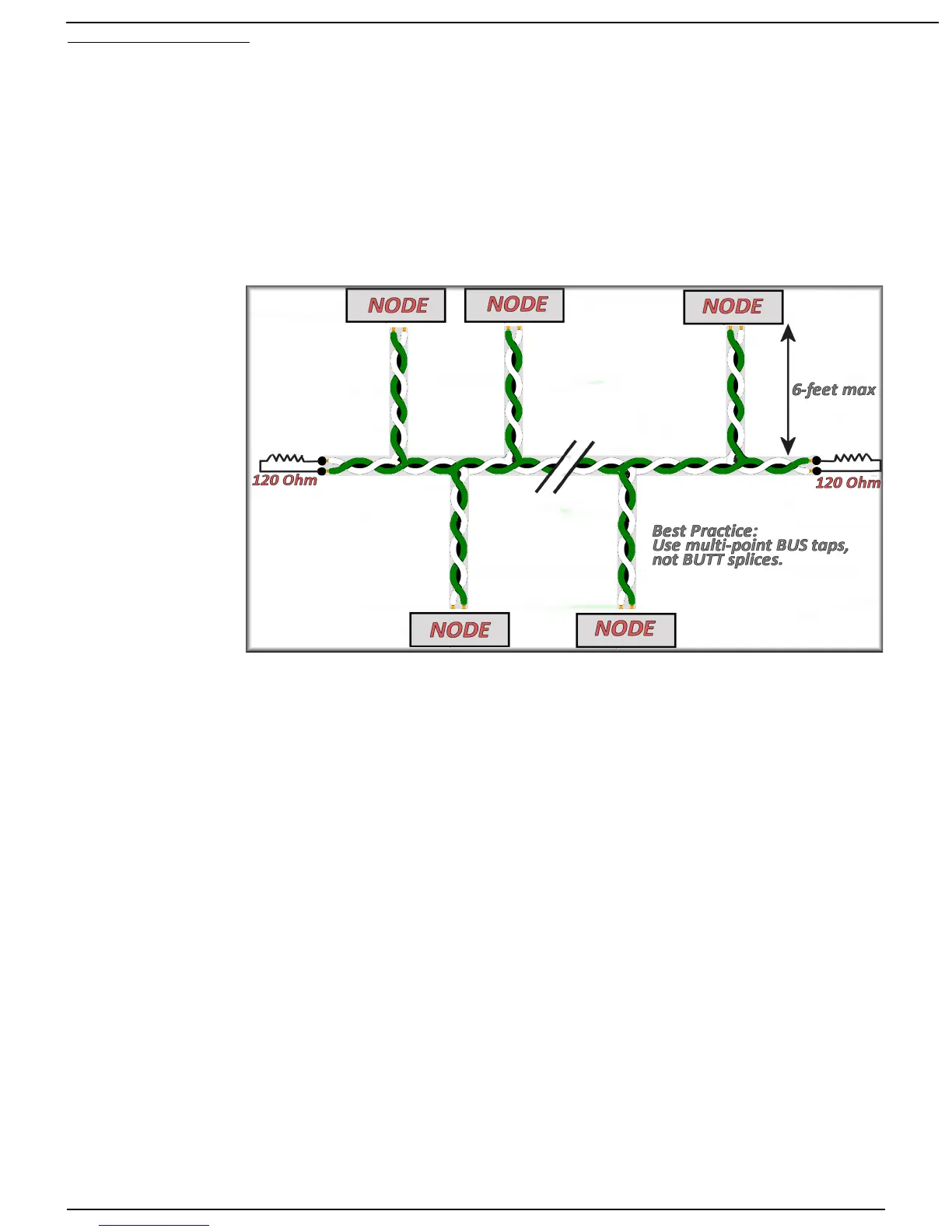
These two wires form a “bus”, connecting each node. The “trunk” of the bus may be quite long,
but the “drops” (lines from trunk to node) are limited to no more than six feet in length. At each
end of the trunk is a 120 ohm resistor connecting the two data lines. These resistors absorb any
“ringing” on the bus.
Each factory RV-
C-equipped coach
should include a
nine-pin circular
connector, located
either under the dash
or in the utility bay.
This connector
allows the service
tool to tap into the
network and become
another node in the
system.
In the event one
wasn't added, a 'T' or
bus-tap must be
used to 'tap in.'
Helpful Hint: When you do an RV-C conversion, include one or two of these sockets to make
installation and maintenance easier. You will likely see this coach again; make it easier now.
Once connected, the service tool can send commands and ask for data from every node in the
system. At this point, you may want to skip directly to “Starting Omniscope.” ...otherwise...
Nodes send commands and messages in small packets. Each packet can contain several
pieces of data - for example, temperature, current, and voltage. Each packet is identified by a
Parameter Group Number, or PGN, and you can determine the contents of the packet by looking
up the PGN in the RV-C documentation. Some PGNs are unique to a certain type of product - e.g.
Slide Rooms use a PGN called SLIDE_STATUS. Some PGNs are common to all products - e.g.
the PRODUCT_ID PGN is universal to all RV-C devices. For the most part you don't need to know
the details of the PGNs to troubleshoot a network. It's the software's job to parse these packets of
data into meaningful values on your screen.
One of the most important PGNs, which is common to all RV-C nodes, is the DM1, or Diagnostic
Message. This message is sent by all nodes to communicate general operating status and
whether any problems have been detected.
Each node has a Source Address, which is used simply to make sure no two nodes talk at the
exact same time. But a node may have more than one function - e.g. an inverter/charger is both
an Inverter and a Charger. These multifunction nodes may display multiple DM1 messages. For
example, the Charger may be Off, while the Inverter is On and displaying a Low DC Voltage
warning. Each DM1 is distinguished by a DSA, or Default Source Address, which shows which
function is being described in the message.
Page 5 10/31/17