9
GB
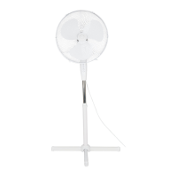
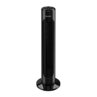
7. Position the rear protective grid5 exact-
ly in the centre and screw it tight with
the screw ring4.
8. Place the rotor blade3 on the axle6,
making sure that the groove on the
back of the rotor blade is positioned ex-
actly on the small pin on the axle.
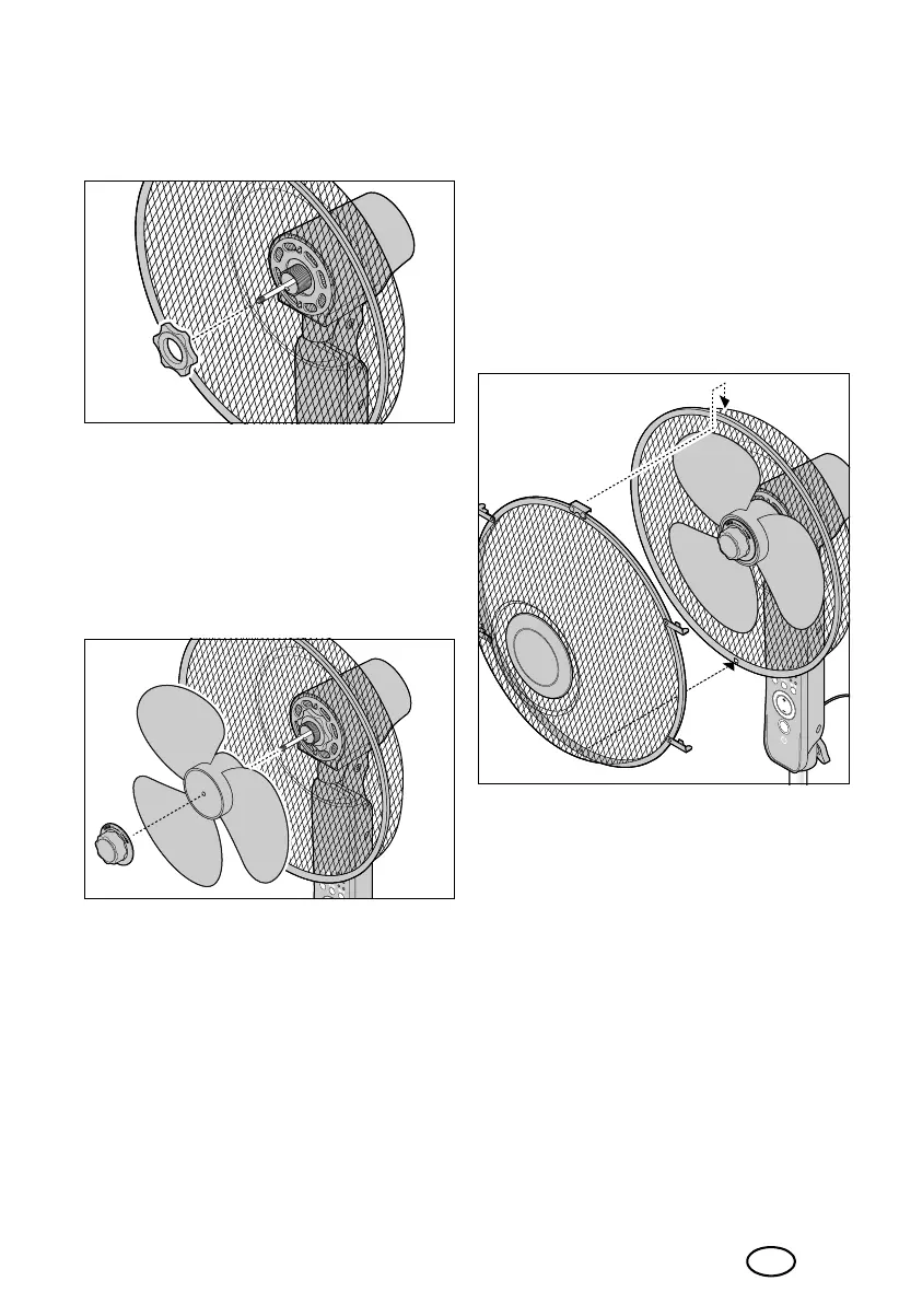
9. Put on the cap nut2 and screw it tight
in the TIGHTEN direction (anticlock-
wise). Hold the rotor blade3 with the
other hand, if necessary.
10. Test whether the rotor blade3 can be
turned freely by hand without touching
other parts. If this is not the case, disas-
semble and reassemble the rear protec-
tive grid5 and the rotor blade3.
11. Place the front protective grid1 onto
the rear protective grid5. Pay attention
to the following:
- The small hook on the edge of the
front protective grid1 is hung over
the top of the edge of the rear protec-
tive grid5.
- The two holes for the connecting
screw18 at the lower edge of the
protective grids1 and5 must be ex-
actly on top of each other.
__353132_2007_StandVentRC_B6.book Seite 9 Dienstag, 26. Januar 2021 1:26 13

 Loading...