8
GB
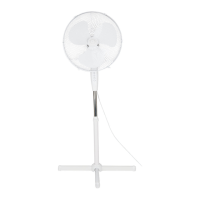
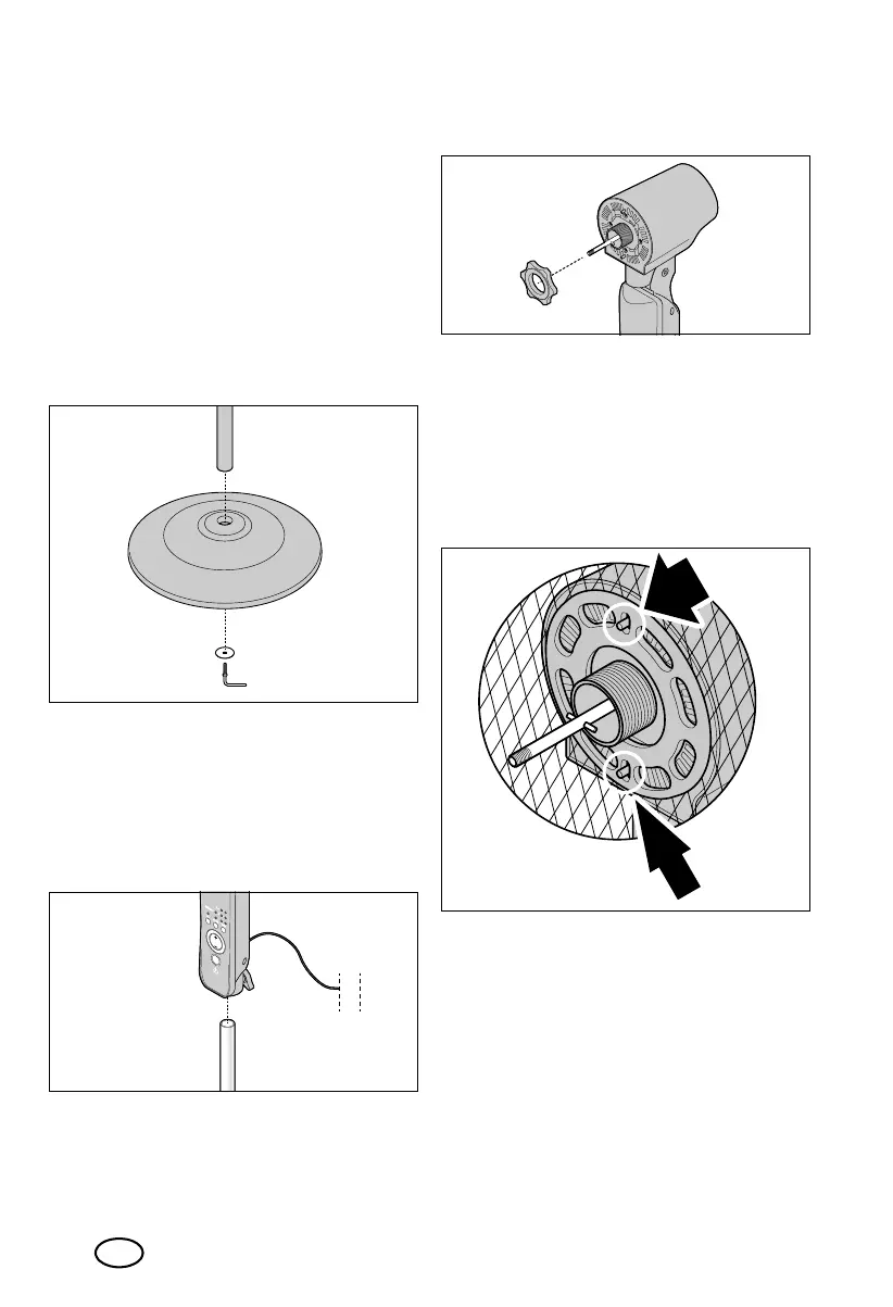
5. Assembling the
device
1. The base plate15 and the L-shape
screw16 are already fitted to the lower
end of the pedestal13 on delivery.
Loosen the L-shape screw and remove
both parts.
2. Place the pedestal
13
on the base
14
.
From the underside of the base, place the
base plate
15
and screw it to the pedes-
tal with the L-shape screw
16
.
3. Unscrew the circlip12 a little (anti-
clockwise). Pull the inner pole11 out of
the pedestal13 a little and screw the
circlip12 back in place (clockwise).
4. Place the top part (control unit8 and
fan motor7) on the inner pole11.
Tighten the locking screw10.
5. The screw ring4 is mounted on the fan
motor7 on delivery. Loosen it.
6. Place the rear protective grid5 on the
fan motor7. Pay attention to the follow-
ing:
- The small hole for the connecting
screw18 is at the bottom.
- The two smaller slots in the middle of
the protective grid are placed on the
ridges on the fan motor.
__353132_2007_StandVentRC_B6.book Seite 8 Dienstag, 26. Januar 2021 1:26 13
 Loading...