3
GB
1. Overview
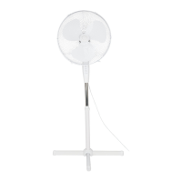
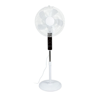
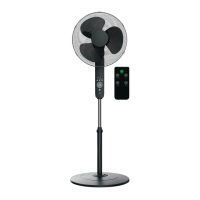
1 Front protective grid
2 Cap nut (for the rotor blade)
3 Rotor blade
4 Screw ring (for the rear protective grid)
5 Rear protective grid
6 Axle (for the rotor blade)
7 Fan motor
8 Control unit (with operating panel)
9 Power cable with mains plug
10 Locking screw
11 Inner pole
12 Circlip
13 Pedestal (height-adjustable)
14 Base
15 Base plate
16 L-shape screw
17 Nut
18 Connecting screw
Figure A: operating panel
19 NOR/NAT/SLP Mode display (Normal/Natural/Sleep)
20 0.5/1/2/4 Timer function display (sum of LEDs: 0.5 - 7.5 hours)
21 LOW/MED/HIGH Fan speed display (low/medium/high)
22 TIMER Timer function button
23 MODE Mode selection button
24 +/– Button for adjusting fan speed (3 fan speeds)
25 On/off switch
26 OSC Button for switching swivel function on/off
27 OSC Swivel function display
Figure B: remote control
28 POWER On/off switch
29 OSC Button for switching swivel function on/off
30 MODE Mode selection button
31 Remote control
32 TIMER Timer function button
33 SPEED Button for adjusting fan speed (3 fan speeds)
__353132_2007_StandVentRC_B6.book Seite 3 Dienstag, 26. Januar 2021 1:26 13
 Loading...
