7. Clean away the old grease from the interior
of the ice breaker and inspect the bearing pressed
into the top of the ice breaker and if worn do not
hesitate to replace it.
8. Inspect the conditions of the O ring; if torn or
worn replace it.
WARNING. The top bearing assembly
works in critical conditions for what
concern its lubrication as it is haused in
the ice breaker where the formation of
condensation is usual. Therefore it is
important to apply on it an ample coating
of Food grade Waterproof Grease before
installing the breaker and cap hook in
place
.
9. Slide off from the auger bottom the upper
half of the water seal.
NOTE. Any time the auger is removed for
replacement or inspection use extra care in
handling the water seal parts, so no dirt or
foreign matters are deposited on the surfaces
of the seal. If there is any doubt about the
effectiveness of the water seal or O ring do
not hesitate to REPLACE THEM.
10. Unloose and remove the three/four bolts
which attach the freezer assy to the aluminium
adaptor.
11. Raise the freezer assy off the adaptor,
secure it out of the way to allow room to work. On
SP125-255 using a suitable lenght and size wooden
dowel or stick inserted through the top of the
open freezer, tap the lower half of the water seal
and the lower bearing out the bottom of the
freezer.
12. On the superflaker models, with two
screwdrivers as a lever, remove from the bottom
of the freezer assy the lo bearing brass holding
ring.
NOTE. It is good practice to replace the water
seal assy and both the top and the bottom
bearings any time the auger is removed.
To facilitate this it is available a service Kit
(P/N 001028.07 for SP125-255 and
P/N 001028.08 for SP N405-6 05- 1205) which
includes besides the above mentioned parts,
the ice breaker O ring and a tube of food
grade waterproof grease.
13. Reach through the adaptor and remove the
coupling parts.
14. Check both the coupling halves for chipping
and wear and do not hesitate to replace them.
15. Install the bottom bearing into its brass
housing paying attention to have the white plastic
ring facing up.
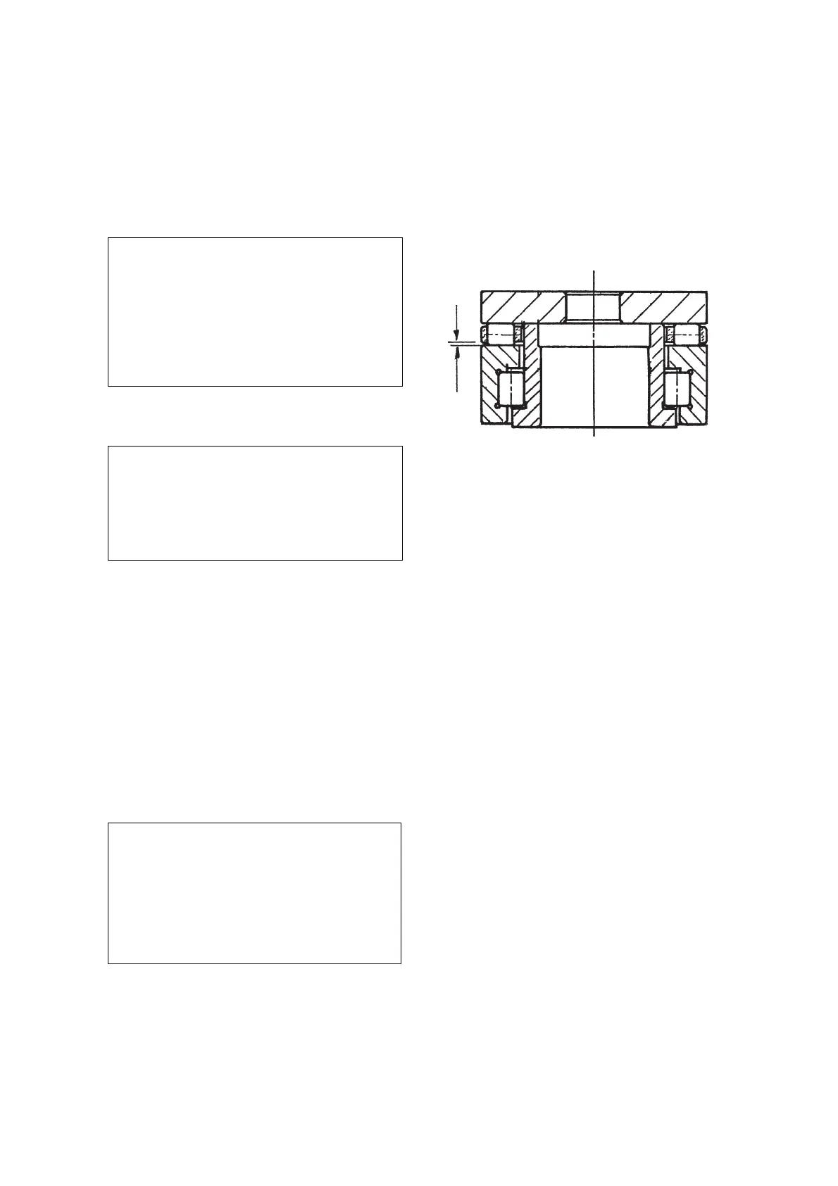
16. Install the upper bearing into the ice breaker
starting by the radial portion that must be fitted
with the flat surface facing up.
17. Apply some lubricant (grease) on the upper
surface then install the rollers cage with the
smaller openings of the same facing up so to
leave a small gap between plastic cage and flat
surface of the botton portion of the bearing (see
drawing).
18. Apply some move lubricant then place the
S.S. trust washer.
19. After to have replace the O ring into the ice
breaker fit the same on top of the auger and
secure it with the top bolt.
20. Install the auger/icebreaker into the
evaporator following the previous steps in
reverse.
J. REPLACEMENT OF THE GEAR MOTOR
ASSY
1. On SP125-255, SP405-605 remove the
front/top and side/rear panels and on SPN1205
remove the front, rear, top and left side panels.
2. Remove the three/four bolts and washers
securing the gear reducer base to the unit chassis,
then remove bolts and lockwashers which attach
the bottom of the aluminium adaptor to the gear
reducer case cover.
3. Follow the steps of item E to remove the
gear motor magnetic sensor.
4. Trace and disconnect the electric wires
leads of the drive motor. Lift and remove the
entire gear motor assembly.
5. To install the replacement gear motor assy
follow the above steps in reverse.
K. REPLACEMENT OF FAN MOTOR
1. Remove the front/top and side/rear panels
on models SP125-255, SPN405-SPN605 and the
front panel on model SPN 1205.
2. Remove screws and yellow green ground
wire. Trace the electrical leads of fan motor and
disconnect them.
Page 32