MOON by Simaudio
Rear Panel Connections
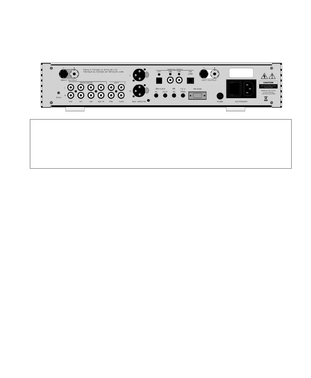
Figure 6 : MOON 340i Rear panel
The rear panel will look similar to Figure 2 (above). There are four (4) pairs of single-ended analog inputs
on RCA connectors labeled CD, A1, A2 and A3/P. The RCA input and output connectors
ontherearpanel have been color coded: ‘white’ for the left channel and ‘red’ for the right channel.
Ifyour MOON 340i is equipped with the optional phono section, the input labeled ‘A3/P’ must beused
to connect your turntable interconnect leads to this integrated amplifier. If you don’t have theoptional
phono section installed, then this input can be used in the same way as the CD, A1 and A2 inputs.
The MOON 340i integrated amplifier also
hastwopairs of non-amplified outputs labeled
“FIX” and “VAR”, located next to the A3/P input.
The ‘FIX’ output is intended as an input
toarecording device such as a cassette tape deck
or CD-Recorder Player. Keep in mind
thattheoutput level is fixed and cannot be
adjusted by the 340i’s volume control. The ‘VAR’
output is designated for output to a power amplifier
with single-ended RCA inputs ifyouwish to use
your MOON 340i only asapreamplifier. Keep in
mind that the output level is variable and adjusted
by the 340i’s volume control.
You will find one pair of XLR balanced inputs
totheright of these non-amplified outputs.
Theseare intended to be used with a source
component that outputs a balanced signal.
For MOON 340i’s equipped with the digital input
option, you will find 4 digital inputs labeled D1, D2,
D3 and D4. The D1 input is on an optical Toslink
connector; both the D2 and D3 inputs areon a S/
PDIF connector; the D4 input isonaUSB type B
connector
Below the area reserved for the optional digital
inputs are a series of input/output connectors
forcustom type installations: From left to right
thereare two (2) “SimLink™” connectors labeled
“in”and “out” on 1/8” mini jacks. Please refer
tothe next section entitled SimLink™ for more
details. Next, there’s a 1/8” mini-jack input for use
with aftermarket infrared remote control receivers.
Then there’s a 12V trigger output ona1/8” mini-
jack that can power up aconnected component
(with a 12V trigger input) at the same time
thatthe340i is powered up. Next, there’safull-
function bi-directional RS-232 port forcustom
integration or automation onaDB9 connector.
Finally on the far right side isthe “ACFuse” socket
cover, the main power switch (“0”=off, “1”=on)
andthe IEC receptacle, labeled “AC Power”
fortheincluded AC powercord.
Don’t hesitate to use high quality interconnect
cables*. Poor quality interconnect cables
candegrade the overall sonic performance
ofyoursystem.