SIMCom GNSS Modules EVB kit User Guide
port, jump the middle and right needle is select K port.
G: UART to USB transceiver.
H: 60 PIN connect to TE board of the navigation SIMcom GNSS module
I: J302, the jumper of VANT which is the source of active of antenna.(
Internal to the antenna
power supply module doesn’t need )
J: Test point area. (Customer should contact SIMCom if the test point is needed).
K: Main UART port for the NMEA output.
L: Debug UART port, reserved.
M: Reset button (for Parts of module).
2.2 USB Interface
There is one Mini-USB interface on SIM68-EVB, which is transferred to UART by a USB to
UART chip CP2103 on the EVB board. User need to install CP2103 driver in their PC first, then
connect the EVB board to the PC by a USB cable, and push S301 up to power the SIM68-EVB.
Please download the latest CP2103 driver according to the PC’s OS from the following link:
http://www.silabs.com/products/mcu/pages/usbtouartbridgevcpdrivers.aspx
or contact SIMCom
for support.
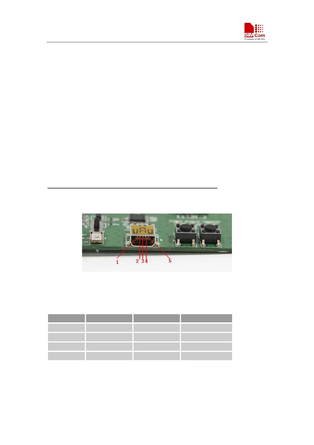
Figure 2: USB interface
Table 1: USB pin definition
PIN Number Signal I/O Description
1 VBUS I 5V input
2 D- I/O Data minus
3 D+ I/O Data plus
4,5 GND GND
SIMCom GNSS Modules EVB Kit User Guide _V1.00 2014-05-20
7