Simplify Communication
SIM7020 Series SUB Kit_User Guide Page 5 / 13
In order to get proper part to do the evaluation test, here is brief list for SIM7020x-SUBKIT part
numbers.
Kit type Part Number Comments
SIM7020C-SUBKIT S2-107ZF For China
SIM7020E-SUBKIT S2-107ZG For Europe, Australia and South Asia etc.
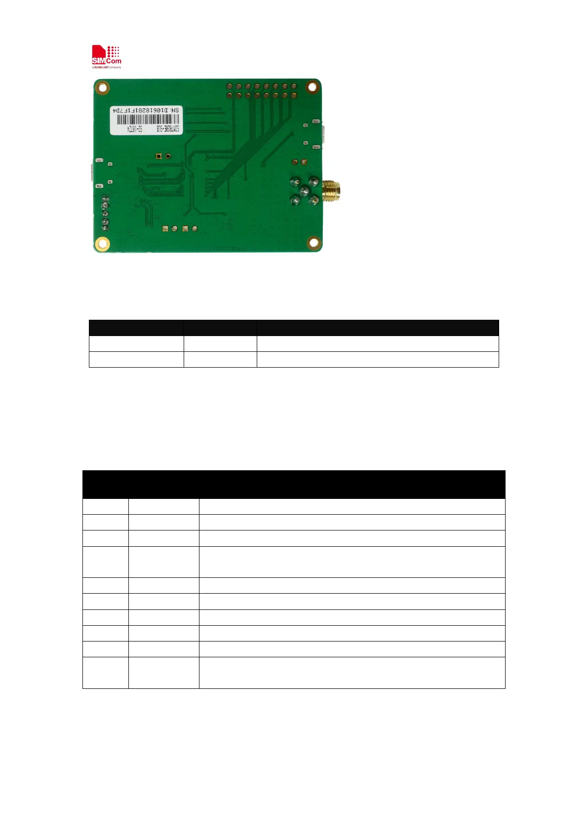
2.2 Interface Introduction
From above overview on the SIM7020x-SUB, we can see many signal interfaces, communication
ports and antenna interface. Now, we will describe them in detail.
Index Position Description
Uxxx SIM7020x Module
SW1 PWRKEY Button
J400 SIM Card holder
J204 1.
UART ports of SIM7020x, for AT communication and FW update.
2. Power Supply
SW2 Power Switch (Left is ON, PWR+ red LED light)
J104 USB port of SIM7020x, for debugging
J3 LTE antenna SMA connector
J1 Reset and GND reserve locations, for resetting the module
J101 DTR and VDD_EXT reserve locations, for sleep mode (AT+CSCLK=1)
J4 RTC_EINT and GND reserve locations, for waking up module from the
PSM mode