Simplify Communication
SIM7020 Series SUB Kit_User Guide Page 8 / 13
contact SIMCom Support Team.
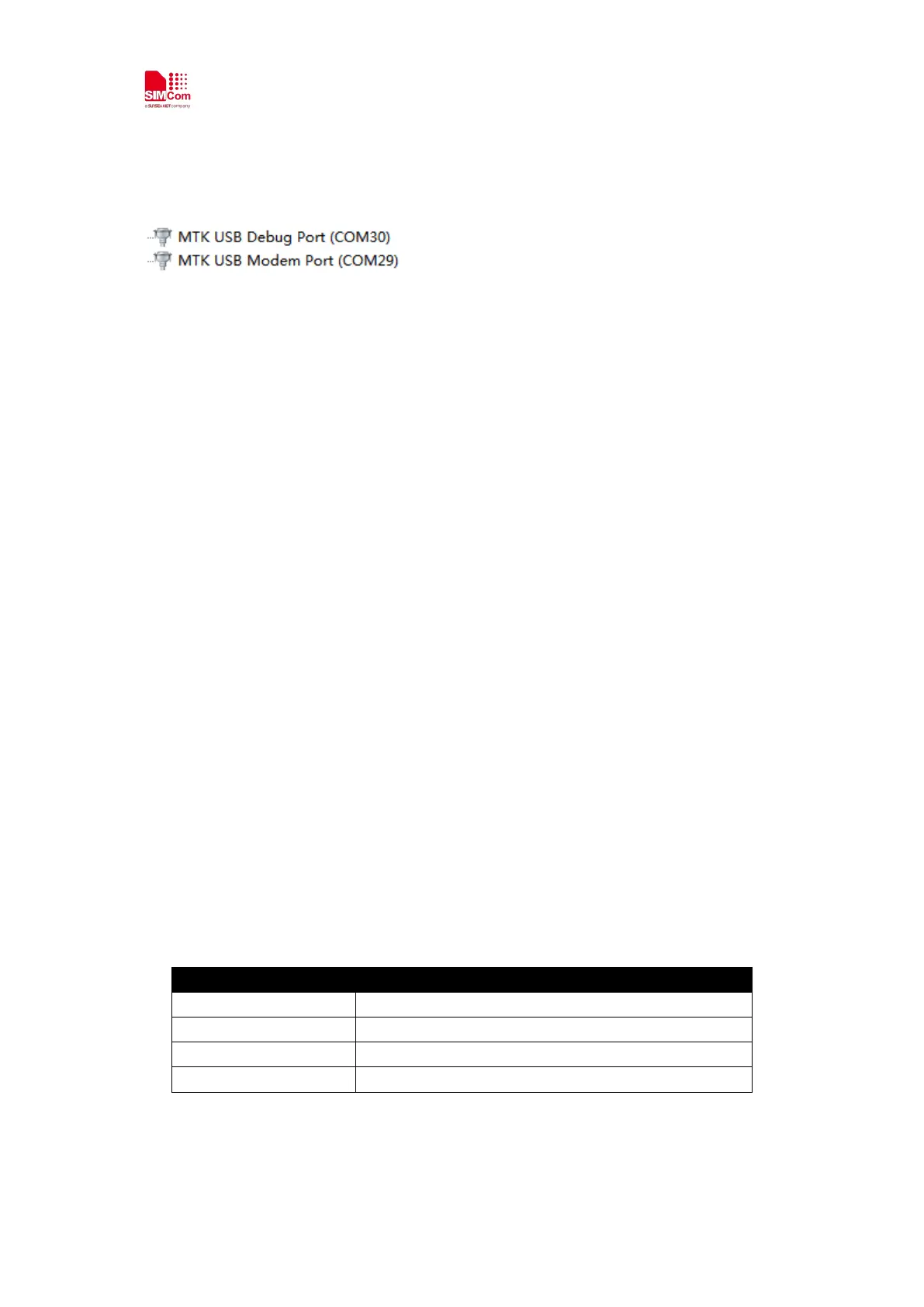
After USB driver installed properly and completely, there will be 2 virtual ports, debug port and
modem port.
USB interface is used for taking genie (debug) log only.
Notes: For the detail, please refer to “SIM7020 Series_Genie_Logging_Tool_User_Guide_V1.0”.
3.2 Accessories installation
Now, in order to do the functional test, necessary accessories need to be installed into SIM7020
SUB board.
1) Insert NBIOTSIM card to sim card slot (position C);
2) Install LTE antenna (position G);
3) Insert micro USB cable to USB jack (position D) for power supply and UART (AT and FW
update) communication;
4) Insert micro USB cable to USB jack (position F) for taking genie log. (Option)
3.3 AT command Communication
3.3.1 Power on device
1) Switch “Power Switch” (Position E) to Left, then PWR+ red LED will light, which means VBAT
power is on.
2) Press “PWRKEY” button (Position B) for one second to power up SIM7020.
Now PWR+ LED light is solid on, while NET+ LED light is blinking with below behaviors.
64ms on, 800ms off Network scanning, not registered
64ms on, 3000ms off Registered network (PS service)
64ms on, 300ms off Data communication
OFF Power off or in PSM mode