Simplify Communication
SIM7020 Series SUB Kit_User Guide Page 7 / 13
※ Notice
Module VBAT range is from 2.1V to 3.6V, typical is 3.3V recommended.
Module GPIO pins are at 1.8V logical level. Cannot be connected to external 3.0V or higher
level signals directly.
SIM7020 series modules are NB1 only, without GNSS technology.
3 Installations and Communication
3.1 Driver installation
There are two USB jacks, one is USB to UART (position D), and the other one is USB (position F).
3.1.1 USB-to-UART interface driver installation
This USB-to-UART chipset on board is from Silicon labs.
Here is the driver link.
https://www.silabs.com/products/development-tools/software/usb-to-uart-bridge-vcp-drivers
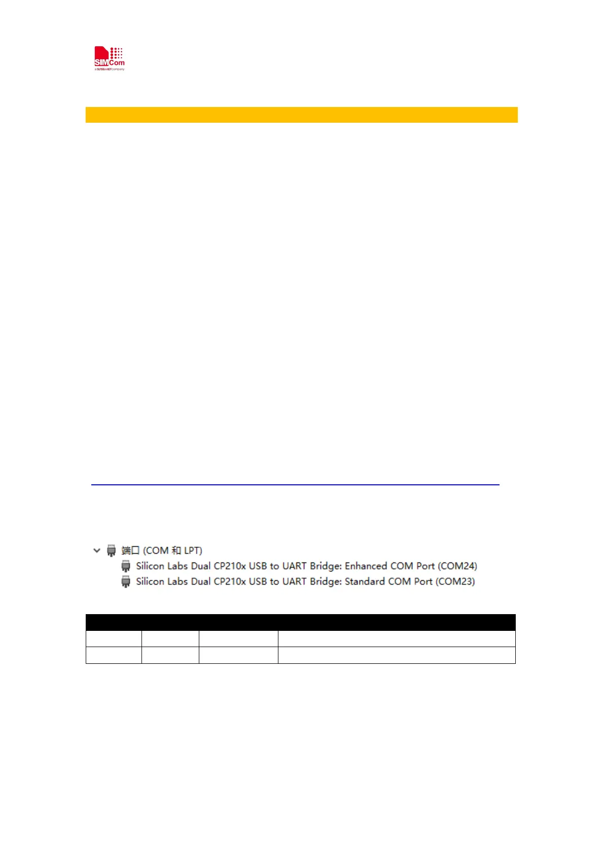
After driver installed properly and completely, there are two virtual USB ports, for example
COM23 and COM24 as below.
Interface Number SIM7020 UART Comments
Enhanced COM 24 UART1 Full mode for AT communication
Standard COM 23 UART2 No hardware flow control, for FW upgrade
3.1.2 Module USB interface driver installation
SIM7020 Chipset is from MTK (MediaTek). SIMCom provide proper driver to developer, please