Smart Machine Smart Decision
SIM800L(MT6261)_Hardware Design_V1.01 36 2016-07-07
will be some cheep noise from speaker output easily. So it is better to put big capacitors and ferrite beads near
audio PA input.
TDD noise has something to do with GND signal. If GND plane is not good, lots of high-frequency noises will
interference microphone and speaker over bypass capacitor. So a good GND during PCB layout could avoid
TDD noise.
4.8. SIM Card Interface
The SIM interface complies with the GSM Phase 1 specification and the new GSM Phase 2+ specification for
FAST 64 kbps SIM card. Both 1.8V and 3.0V SIM card are supported. The SIM interface is powered from an
internal regulator in the module.
4.8.1. SIM Card Application
Table 17: SIM pin definition
Pin name Pin number Function
SIM_VDD 16 Voltage supply for SIM card. Support 1.8V or 3V SIM card
SIM _ D ATA 14 SIM data input/output
SIM_CLK 55 SIM clock
SIM_RST 15 SIM reset
It is recommended to use an ESD protection component such as ST (
www.st.com ) ESDA6V1-5W6 or ON
SEMI (
www.onsemi.com ) SMF05C. That the SIM peripheral circuit should be close to the SIM card socket.
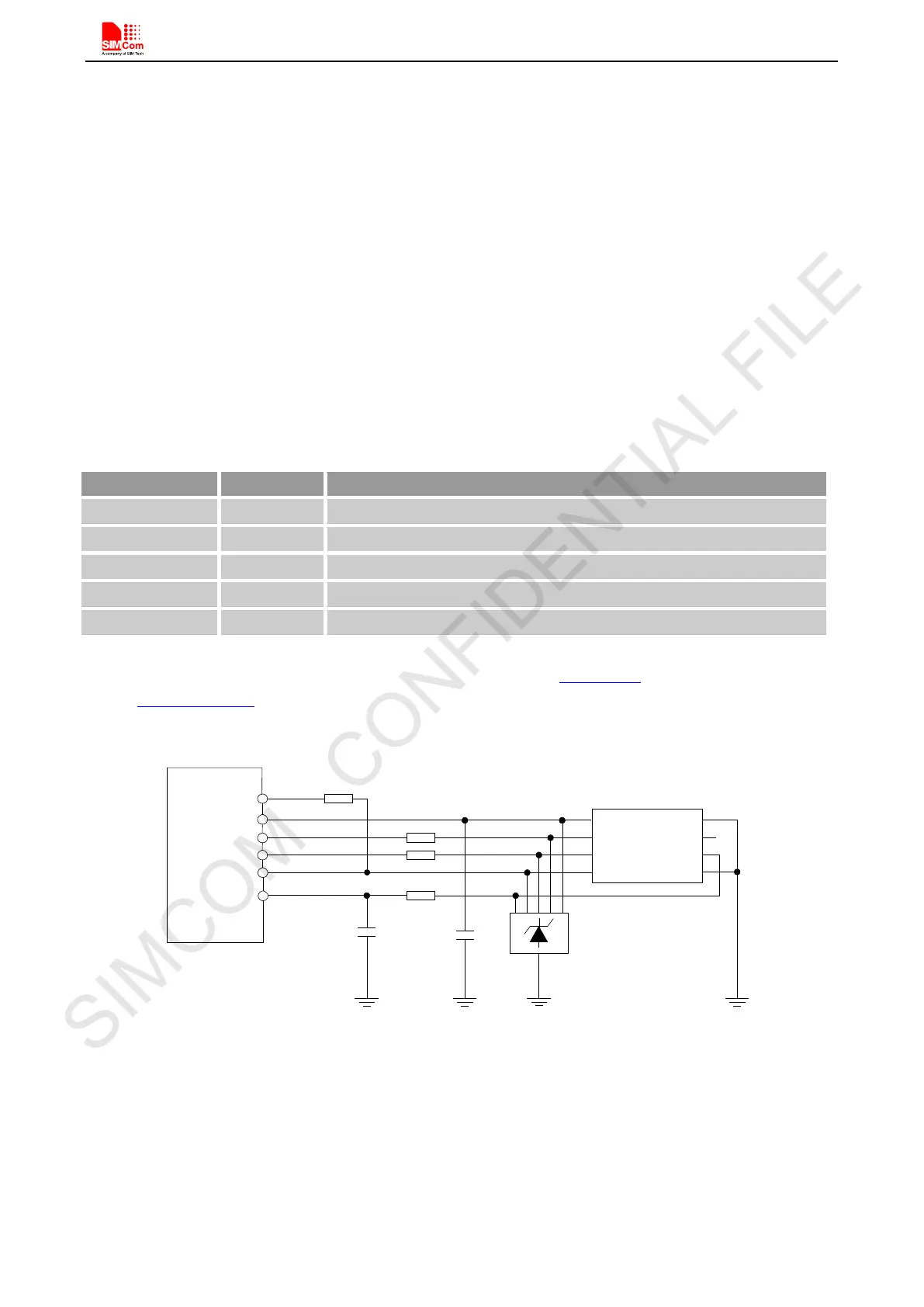
The reference circuit of the 8-pin SIM card holder is illustrated in the following figure.
Module
PRESENCE
100nF
MOLEX-91228
SIM Card
22pF
VCC
GND
RST
VPP
CLK I/O
GND
VDD_EXT
SIM_VDD
SIM_RST
SIM_CLK
SIM_DATA
4.7K
ESDA6V1
SIM_DET
51Ω
51Ω
51Ω
Figure 32: Reference circuit of the 8-pin SIM card holder
The SIM_DET pin is used for detection of the SIM card hot plug in. Customer can select the 8-pin SIM card
holder to implement SIM card detection function. AT command “AT+CSDT” is used to enable or disable SIM
card detection function. For details of this AT command, please refer to document [1].
If the SIM card detection function is not used, customer can keep the SIM_DET pin open. The reference circuit
of 6-pin SIM card holder is illustrated in the following figure.