Smart Machine Smart Decision
SIM800L(MT6261)_Hardware Design_V1.01 48 2016-07-07
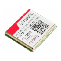
R101,C101,C102 are the matching circuit, the value should be defined by the antenna design. Normally R101 is
0Ω, C101 and C102 are not mounted. The RF connector is used for conduction test. If the space between RF pin
and antenna is not enough, the matching circuit should be designed as in the following figure:
Module
R101
GSM_ANT
(Pin40)
C101
C102
GND
(Pin41)
GND
(Pin39)
GSM
Antenna
D101
Figure 47: GSM simple antenna matching circuit
Normally R101 is 0Ω, C101 and C102 are not mounted.
D101 in Figure 46 and Figure 47 is used for ESD to protect antenna. In order to avoid damaging the module,
TVS can be used. The TVS suggested can refer to Table 35.
Table 35: Recommended transient voltage suppressor
2 Marata LXES15AAA1-153 0402
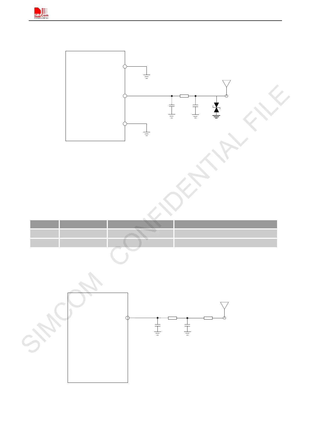
4.19.2. FM Antenna Interface
The module provides 1 FM antenna pad named FM_ANT . The FM antenna interface circuit is recommended as
following:
Moudle
FM_ANT
R303
C303
C304
R304
FM
Antenna
Figure 48: FM antenna matching circuit
Normally, R303\R304 are 0Ω, C303\C304 are not mounted.