Smart Machine Smart Decision
SIM800L(MT6261)_Hardware Design_V1.01 46 2016-07-07
Pin name Pin number Description
S TAT U S 4 Operating status indication
Note: For timing about STATUS, please reference to the chapter “4.2 power on/down scenarios”
4.17. LED Interface
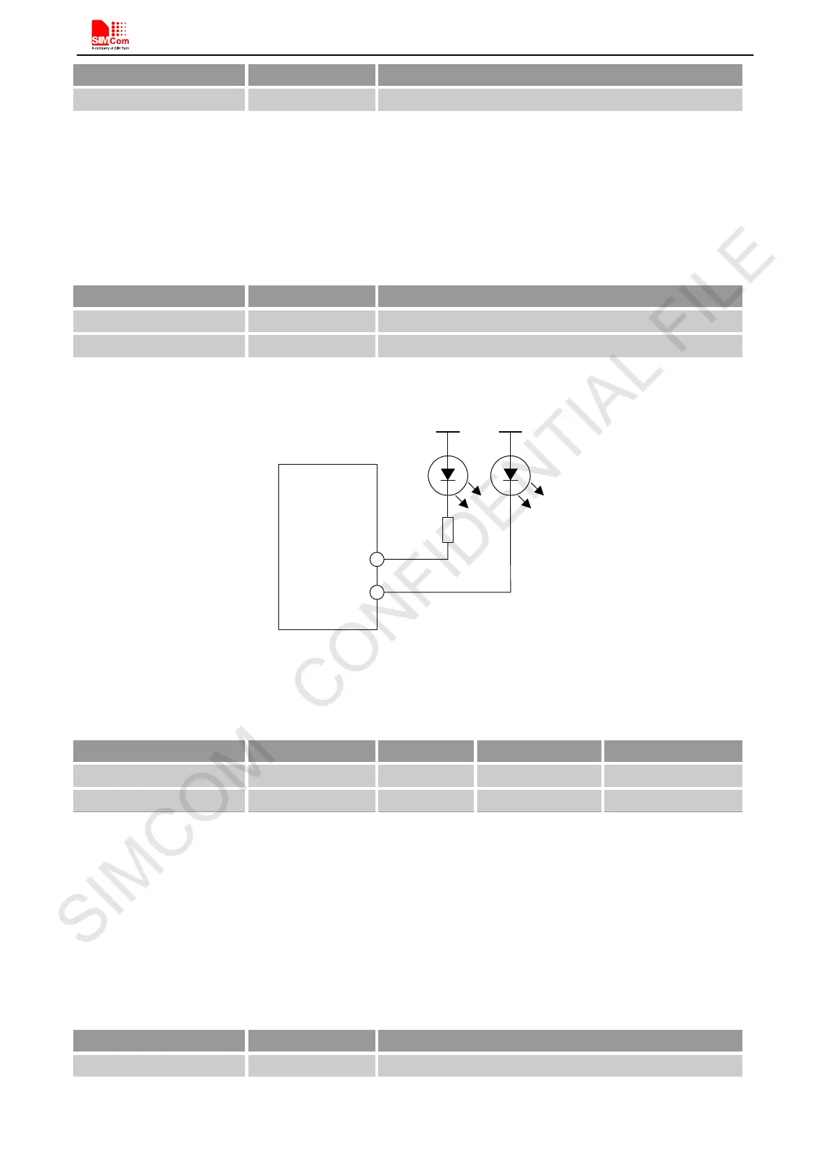
SIM800L provides two LED driver pin. The two pin are open-drain output.
Table 32: Pin definition of the LED
Reference circuit is recommended in the following figure:
Module
ISINK0
VBAT VBAT
R
ISINK1
Figure 44: LED driver reference circuit
Table 33: ISINK specification
ISINK1 60 - 100 mA
Note: ISINK0 provide 6-current- level steps of up to 24mA.
4.18. RF Synchronization Signal
The synchronization signal serves to indicate growing power consumption during the transmit burst. The signal
is generated by the RF_SYNC pin.
Table 34: Definition of the RF_SYNC pin
Pin name Pin number Description
ISINK0 47 Sink current for LCM module
ISINK1 46 Sink current for keypad LED
RF_SYNC 5 Transmit synchronization signal