12
This means that the efficiency of the
system will deteriorate as corrosion
sludge accumulates within the system,
risking damage to pump and valves, boil-
er noise and circulation problems.
–
For optimum performance after instal-
lation this boiler and its associated cen-
tral heating system must be flushed in
accordance with the guidelines given in
BS 7593 “Treatment of water in
domestic hot water central heating
systems”.
Sime Ltd recommend only the use of
FERNOX products for the flushing and
final treatment of the system water.
This is particularly important in hard
water areas.
Artificially softened water must not be
used to fill the heating system.
Failure to flush and addinhibitor to the
system may invalidatethe appliance
warranty. For the correct operation of
the aluminum heat exchanger make
sure that the chemical/physics char-
acteristics of the system water have a
PH value within 6,5 and 8.
– It is important to check the inhibitor
concentration after installation, system
modification and at every service in
accordance with the manufacturer’s
instructions (Test kits are available from
inhibitor stockists).
– At every service the Aquaguard Filter
(4.5.2) should be checked and cleaned.
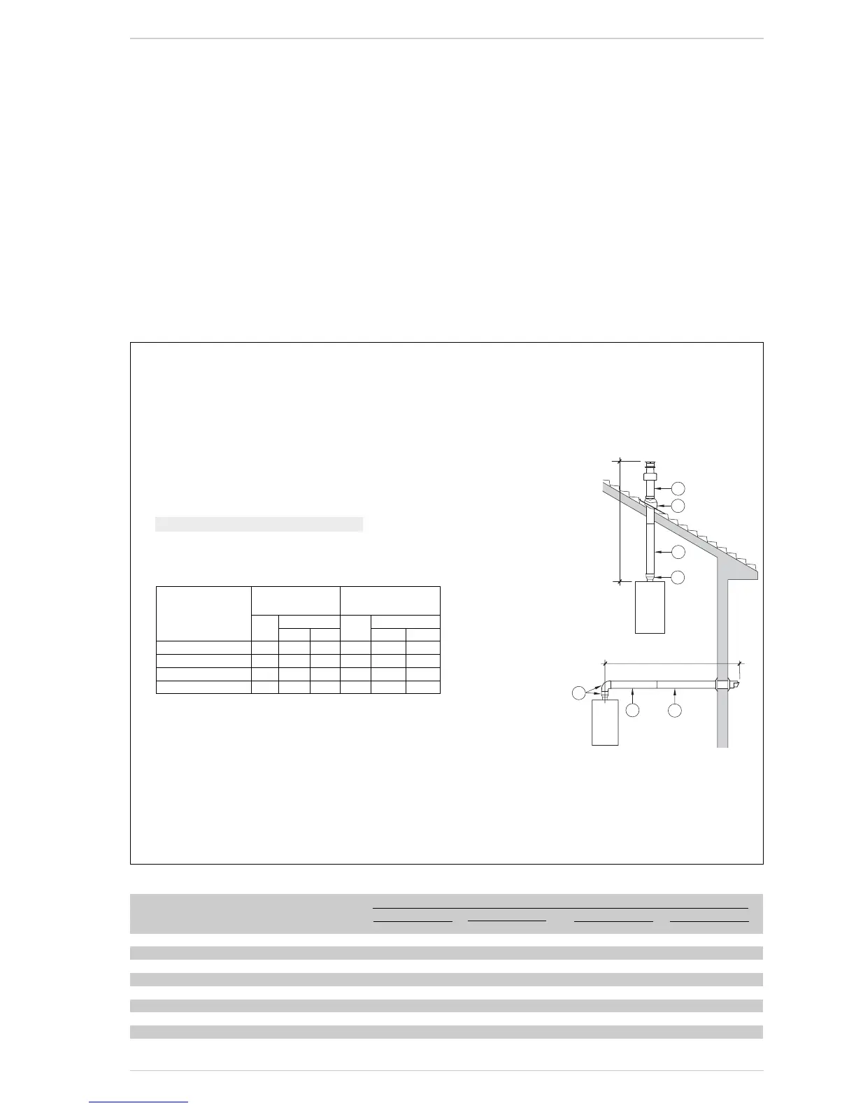
2.5 INSTALLATION OF
COAXIAL DUCT
ø 60/100 - ø 80/125
(fig. 6)
The coaxial suction and discharge pipes are
supplied in a special kit (that can be purcha-
sed separately) along with assembly
instructions.
The diagrams of fig. 6 illustrate some
examples of different types of fluing options
allowed and the maximum lengths that can
be reached.
LIST OF ø 60/100 ACCESSORIES
1 Coaxial duct kit L. 790 code 8 091212
(includes 8086950)
2a Extension L. 1000 code 8096150
2b Extension L. 500 code 8096151
3 Vertical extension L. 140 with coupling code 8086950
5 Tile for joint code 8091300
6 Terminal for roof exit L. 1285 code 8091212
(includes 8086950)
Model Length of pipe Length of pipe
ø 60/100 ø 80/125
HV H V
Min Max Min Max
20 SYSTEM 6 m 1.3 m 8 m 12 m 1.2 m 15 m
25 6 m 1.3 m 8 m 12 m 1.2 m 15 m
30 5 m 1.3 m 7 m 10 m 1.2 m 13 m
35 4 m 1.3 m 6 m 10 m 1.2 m 13 m
LIST OF ø 80/125 ACCESSORIES
1 Coaxial duct kit L. 785 code 8091205A
(includes 8093150)
2a Extension L. 1000 code 8096171
2b Extension L. 500 code 8096170
3 Adapter for ø 80/125 code 8093150
5 Tile for joint code 8091300
6 Terminal for roof exit L. 1285 code 8091205A
(includes 8093150)
H (Horizontal) m
V (Vertical) m
IMPORTANT:
– The insertion of each additional 90° bend with a diameter of 60/100 (code 8095850)
reduces the available section by 1.5 meters.
– The insertion of each additional 90° bend with a diameter of 80/125 (code 8095870)
reduces the available section by 2 meters.
– Each additional 45° curve installed a diameter of 60/100 (code 8095550) reduces the
available length by 1.0 metres.
– Each additional 45° curve installed a diameter of 80/125 (code 8095970) reduces the
available length by 1.0 metres.
HORIZONTAL FLUES MUST BE LEVEL
NOTE: Before connecting accessories, it is always advisable to lubricate the internal part of
the gaskets with silicon products. Avoid using oils and greases.
TABLE 3 - ACCESSORIES ø 80
Accessories ø 80 Total head loss (
mm H
2
O)
20 25 30 35
Inlet Outlet Inlet Outlet Inlet Outlet Inlet Outlet
Air/smoke divider – – – – – – – –
90° elbow MF 0.15 0.20 0.20 0.25 0.25 0.30 0.30 0.40
45° elbow MF 0.10 0.10 0.15 0.15 0.20 0.20 0.25 0.25
Extension L. 1000 (horizontal) 0.10 0.10 0.15 0.15 0.20 0.20 0.25 0.25
Extension L. 1000 (vertical) 0.10 0.10 0.15 0.15 0.20 0.20 0,25 0.25
Wall terminal 0.05 0.20 0.10 0.25 0.10 0.35 0.15 0.50
Wall coaxial exhaust
*
Roof outlet terminal * 0.50 0.05 0.80 0.10 1.10 0.15 1.50 0.20
* This loss includes the loss of the adaptor 8091401
Fig. 6

 Loading...