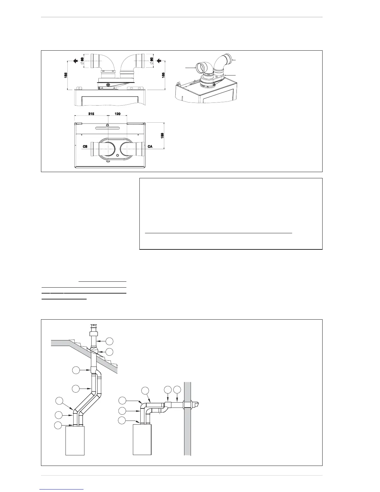
2.6 INSTALLATION OF SEPARATE
DUCTS ø 80 (fig. 7 - fig. 7/a)
The kit with dedicated pipes enables to
separate the exhaust fumes pipes from the
air suction pipes (fig. 7):
–for ø 80 pipes, divider code 8093050 is
provided upon request.
The maximum overall length, resulting
from the sum of all the suction and
discharge pipes, is determined by the
load losses of the single connected acces-
sories and should not exceed 13 mm H2O
(version 20 System) - 15 mm H2O (ver-
sion 25-30-35) (ATTENTION: the total
length of each pipe should not exceed 50
m, even if the total loss is below the
maxi-
mum applicable loss.)
See Table 3 for information on the load los-
ses of single accessories and the example
of Fig. 7/a for information on how to calcu-
late load losses.
2.6.1 Separate ducts kit (fig. 8)
The diagrams of Figure 8 show a couple of
examples of the permitted exhausts confi-
gurations.
2.7 POSITIONING THE
OUTLET TERMINALS (fig. 9)
The outlet terminals for forced-draught
appliances may be located in the external
perimeter walls of the building.
To provide some indications of possible solu-
tions, Table 4 gives the minimum distances
to be observed, with reference to the type
of building shown in fig. 9.
NOTE
Before connecting accessories, it is always advisable to
lubricate the internal part of the gaskets with silicon
products. Avoid using oils and greases.
LIST OF ø 80 ACCESSORIES
1 Air/smoke divider code 8093050
3 a Extension L. 1000 code 8077351 (6 pz.)
3 b Extension L. 500 code 8077350 (6 pz.)
7 a Additional 45° MF curve code 8077451(6 pz.)
7 b Additional 90° MF curve code 8077450 (6 pz.)
9 Manifold, code 8091401
10 Tile for joint code 8091300
11 Terminal for roof exit L. 1381 code 8091205B
13 Union suction/exhaust code 8091401
14 Coaxial exhaust ø 80/125 L. 885 code 8096253

 Loading...