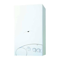
– If the terminal discharges into a pathway or passageway check
that combustion products will not cause nuisance and that the
terminal will not obstruct the passageway.
– Where the lowest part of the terminal is fitted less than 2 m
(78 in) above ground, above a balcony or above a flat roof to
which people have access, the terminal MUST be protected by
a purpose designed guard.
– Where the terminal is fitted within 850 mm (34 in) of a plastic
or painted gutter, or 450 mm (18 in) of painted eaves, an alu-
minium shield at least 1,500 mm (59 in) long must be fitted to
the underside of the painted surface.
– The air inlet/outlet flue duct MUST NOT be closer than 25 mm
(1 in) to combustible material.
– In certain weather conditions the terminal may emit a plume of
steam. This is normal but positions where this would cause a
nuisance should be avoided.
Terminal position Minimum spacing
A Directly below an openable window, air vent
or any other ventilation opening 300 mm 12 in
B Below guttering, drain pipes or soil pipes (*) 75 mm 3 in
C/D Below eaves, balconies or carport roof 200 mm 8 in
E From vertical drain pipes or soil pipes 75 mm 3 in
F From internal or external corners 300 mm 12 in
G Above adjacent ground, roof or balcony level 300 mm 12 in
H From a boundary or surface facing the boiler 600 mm 24 in
I From a terminal facing the terminal 1,200 mm 48 in
J From an opening in the carport
(eg door, window into dwelling) 1,200 mm 48 in
K Vertically from a terminal on the same wall 1,500 mm 60 in
L Horizontally from a terminal on the same wall 300 mm 12 in
M Horizontally from a vertical terminal to a wall 300 mm 12 in
N Horizontally from an openable window or other opening 300 mm 12 in
P Above an openable window or other opening 300 mm 12 in
Q From an adjacent vertical terminal 600 mm 24 in
(*) For condensing boilers this distance can be reduced to 25 mm without effecting boiler per-
formance, but it will be necessary to protect the surfaces from the effects of condensate
TABLE 4
Fig. 9
14
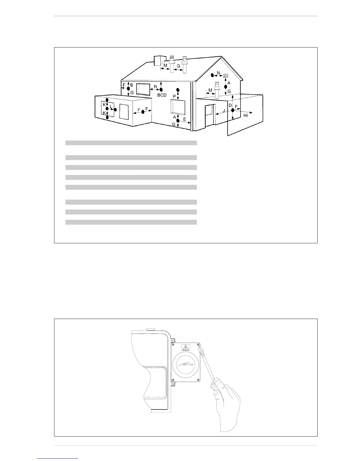
2.8 INSTRUCTIONS FOR
ASSEMBLY OPTIONAL
CLOCK PART
NUMBER 8092242
(fig. 23/a - 23/b - 23/c)
1) Isolate the power supply to the
boiler.
2) Remove the boiler cover.
3) Remove the time clock box cover
unscrewing the 4 screws (fig.
23/a).
IMPORTANT! RETAIN THE 4
SCREWS AS THESE ARE USED TO
FIX TIME CLOCK!
4) Inside the time clock box are 4
wires:
- 2 reds
- 1 brown
- 1 blue;
Remove the faston protections
and connect as shown on fig.
23/b.
5) Fix the Time clock with the 4
screws removed before (as
shown on fig. 23/c).
Fig. 23/a

 Loading...