TRANSPONDER MONITOR PO#W.OP~F@f%lQN
Each monitor point can be prepared for one of three types of operation: NORMAL, LATCH, or KEY. A
description of the use of each type of operation is as follows:
NORMAL -
This type of monitor point operation is used with sensing devices that latch into alarm; e.g.,
pull stations and smoke detectors. In this mode of operation, the transponder circuitry will
follow the action of the sensing device, resetting as soon as the sensing device is reset.
LATCH -
This type of monitor point operation is used with sensing devices that may give only a mo-
mentary alarm indication and do not latch into alarm; e.g., security devices such as,door
switches. In this mode of operation the transponder circuitry will latch in the alarm state,
resetting only after the alarm has been recognized by the Central Control Console.
.
KEY -
This type of operation can be used with both momentary and latching sensing devices. In
this mode of operation, when a sensing device goes into alarm, the transponder circuitry
will latch in the alarm state and remain latched until a keyswitch for that monitor point is
momentarily activated. This insures that an alarm can only be reset by authorized personnel.
Monitor oint operation is predetermined and is listed on the Transponder Specification Sheet (Figure 1,
Item
6
b ). NORMAL and LATCH modes of operation are determined by jumper placement at the fac-
tory. For KEY operation, a keyswitch must be wired in at the time of installation.
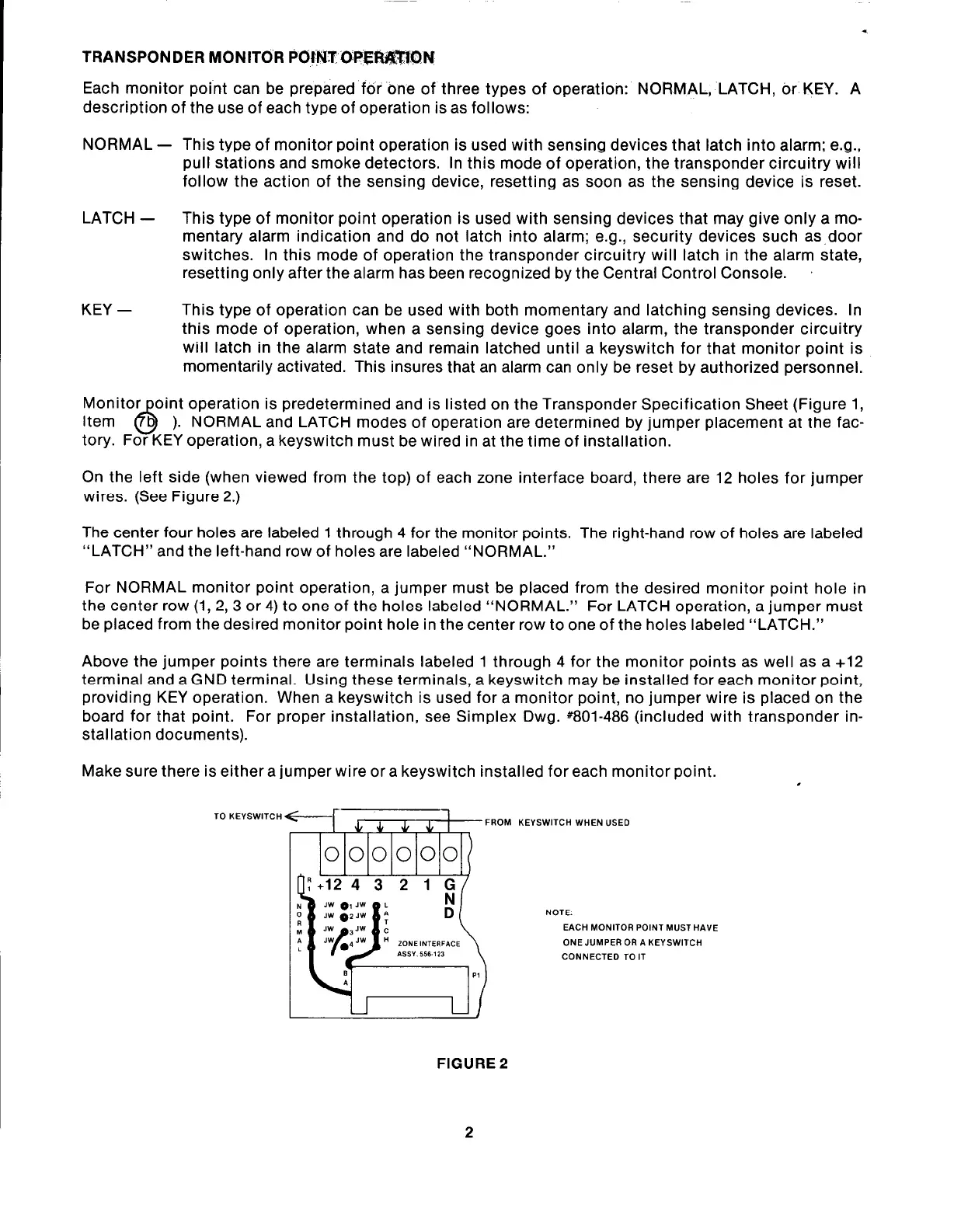
On the left side (when viewed from the top) of each zone interface board, there are 12 holes for jumper
wires. (See Figure 2.)
The center four holes are labeled 1 through 4 for the monitor points. The right-hand row of holes are labeled
“LATCH” and the left-hand row of holes are labeled “NORMAL.”
For NORMAL monitor point operation, a jumper must be placed from the desired monitor point hole in
the center row (1, 2, 3 or 4) to one of the holes labeled “NORMAL.”
For LATCH operation, a jumper must
be placed from the desired monitor point hole in the center row to one of the holes labeled “LATCH.”
Above the jumper points there are terminals labeled 1 through 4 for the monitor points as well as a +12
terminal and a GND terminal. Using these terminals, a keyswitch may be installed for each monitor point,
providing KEY operation. When a keyswitch is used for a monitor point, no jumper wire is placed on the
board for that point. For proper installation, see Simplex Dwg.
#801-486 (included with transponder in-
stallation documents).
Make sure there is either a jumper wire or a keyswitch installed for each monitor point.
,
TO KEYSWI ITCH
r7iTi-z
FROM L
000000
:EYSWITCH WHEN USED
NOTE:
EACH MONITOR POINT MUST HP
ONE JUMPER OR A KEYSWITCH
CONNECTED TO IT
IVE
FIGURE 2
2