INTRUDUCTION
This publication contains information on jumper wire connections and switch settings used in the 2100
Multiplex system. The information can be used either to verify that newly installed equipment meets its
specifications or to modify new or existing equipment.
JUMPER PLACEMENT
TRANSPONDER JUMPER PLACEMENT
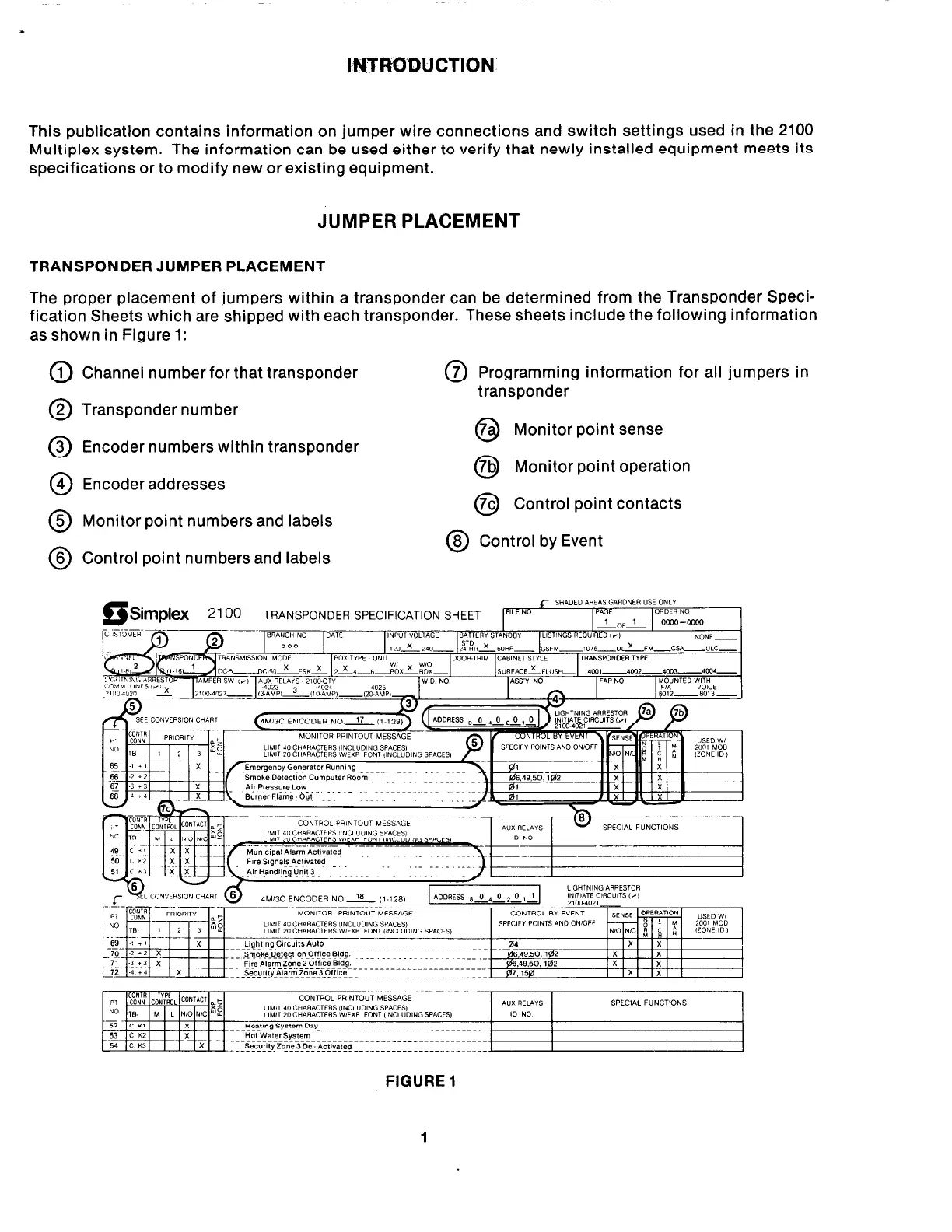
The proper placement of ,jumpers within a transponder can be determined from the Transponder Speci-
fication Sheets which are shipped with each transponder. These sheets include the following information
as shown in Figure 1:
0
1 Channel number for that transponder
0
2 Transponder number
0
3 Encoder numbers within transponder
0
4 Encoder addresses
0
7 Programming information for all jumpers in
transponder
Monitor point sense
Q
0
7b Monitor point operation
0
0
7c Control point contacts
5 Monitor point numbers and labels
0
0
8 Control by Event
6 Control point numbers and labels
I !%lpkX 2100 TRANSPONDER SPECIFICATION SHEET F’LENo
J- SHADEDAREAS(;ARDNER USEONLY
PAGE
ORDER NO
l0F-L
0000 --oocm
BATTERY STANDBY LISTINGS REO”IRED ,*,
-~
4M13C ENCODER NO 18 (I-128)
FIGURE 1
1