CENTRAL CONTRdL CONSOLE C~~A~~NEL-&‘I’A;NN‘UNCIATOR EiAUD’RAf’E
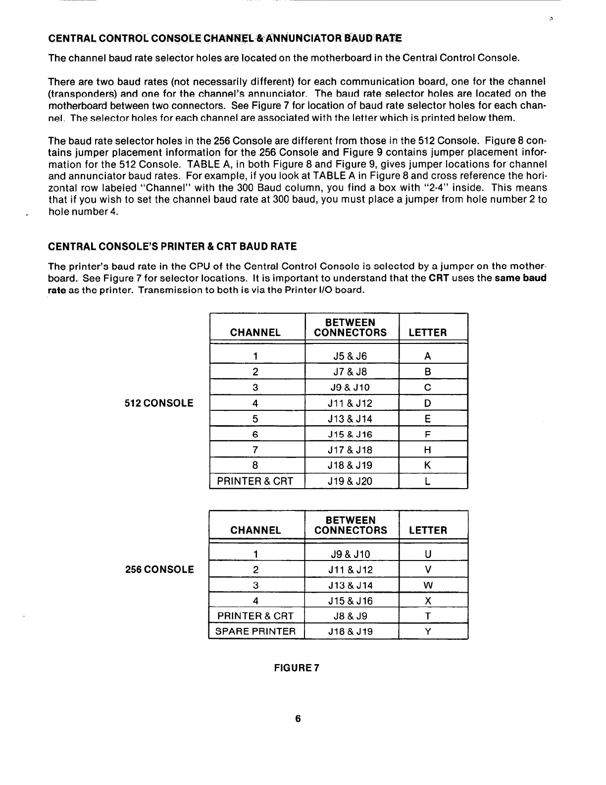
The channel baud rate selector holes are located on the motherboard in the Central Control Console.
There are two baud rates (not necessarily different) for each communication board, one for the channel
(transponders) and one for the channel’s annunciator. The baud rate selector holes are located on the
motherboard between two connectors. See Figure 7 for location of baud rate selector holes for each chan-
nel. The selector holes for each channel are associated with the letter which is printed below them.
The baud rate selector holes in the 256 Console are different from those in the 512 Console. Figure 8 con-
tains jumper placement information for the 256 Console and Figure 9 contains jumper placement infor-
mation for the 512 Console. TABLE A, in both Figure 8 and Figure 9, gives jumper locations for channel
and annunciator baud rates. For example, if you look at TABLE A in Figure 8 and cross reference the hori-
zontal row labeled “Channel” with the 300 Baud column, you find a box with “2-4” inside. This means
that if you wish to set the channel baud rate at 300 baud, you must place a jumper from hole number 2 to
hole number 4.
CENTRAL CONSOLE’S PRINTER &CRT BAUD RATE
The printer’s baud rate in the CPU of the Central Control Console is selected by a jumper on the mother-
board. See Figure 7 for selector locations. It is important to understand that the CRT uses the same baud
rate as the printer. Transmission to both is via the Printer l/O board.
512 CONSOLE
I I
BETWEEN
CHANNEL CONNECTORS
I
LETTER
I
t
I I
I
I
I
1
I
J5&J6
I
A
I
2 J7&J8 B
3 J9&JlO C
I 4
t Jll &J12 1 D 1
I 5
1 J13&J14 I E 1
I
7
I
J17&J18 I H I
8 J18& J19 K
PRINTER &CRT
J19 8. J20 L
256 CONSOLE
FIGURE 7