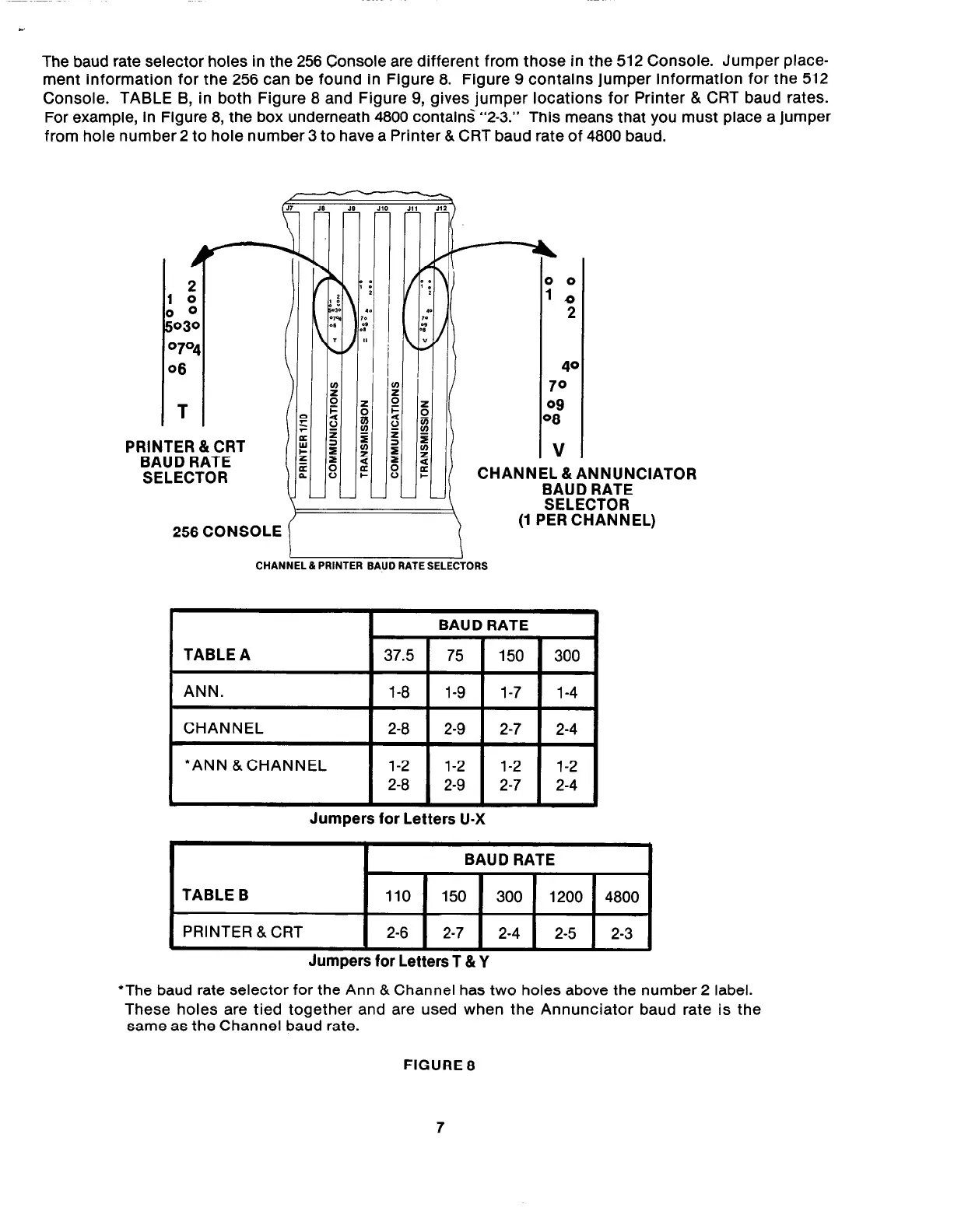
The baud rate selector holes in the 256 Console are different from those in the 512 Console. Jumper place-
ment information for the 256 can be found in Figure 8. Figure 9 contains jumper information for the 512
Console. TABLE B, in both Figure 8 and Figure 9, gives jumper locations for Printer & CRT baud rates.
For example, in Figure 8, the box underneath 4800 contain< “2-3.”
This means that you must place a jumper
from hole number 2 to hole number 3 to have a Printer & CRT baud rate of 4800 baud.
PRINTER &CRT
BAUD RATE
SELECTOR
ANNUNCIATOR
BAUD RATE
CHANNEL & PRINTER BAUD RATE SELECTORS
I
TABLE A
I
ANN.
1 l-8 1 1-9 1 1-7 1 l-4 1
I
CHANNEL
1 2-8 1 2-9 1 2-7 1 2-4 1
I
*ANN &CHANNEL
Jumpers for Letters U-X
I
I
BAUD RATE
I
TABLE B
110 150
300 1200
4800
PRINTER &CRT
2-6 2-7
2-4
2-5
2-3
Jumpers for Letters T &Y
*The baud rate selector for the Ann & Channel has two holes above the number 2 label.
These holes are tied together and are used when the Annunciator baud rate is the
same as the Channel baud rate.
FIGURE 8
7