ENCODER BOARD ADDRESS
On the transponder motherboard, immediately above,the monitor point status select holes, are twelve
holes labeled “ADDRESS SELECT.” See Figure 4.
Four of the holes are labeled in a straight binary code fashion. Code 1 indicates the least significant bit,
2 indicates the next bit, 4 indicates the third bit, and 8 indicates the most significant bit. A jumper must
go from each of these holes to either a hole labeled 12VDC (placing the bit HIGH) or to a hole labeled GND
(placing the bit LOW). The sum of all the HIGH bits is the encoder address. (See “Encoder Conversion
Chart” in the 2100 Multiplex Installation Manual.)
A 4-bit binary code provides a maximum of 16 different addresses (00 thru 15). An encoder’s address can
be verified by checking the Transponder Specification Sheet. (See Figure 1, Item @ ).
TRANSPONDER BAUD RATE
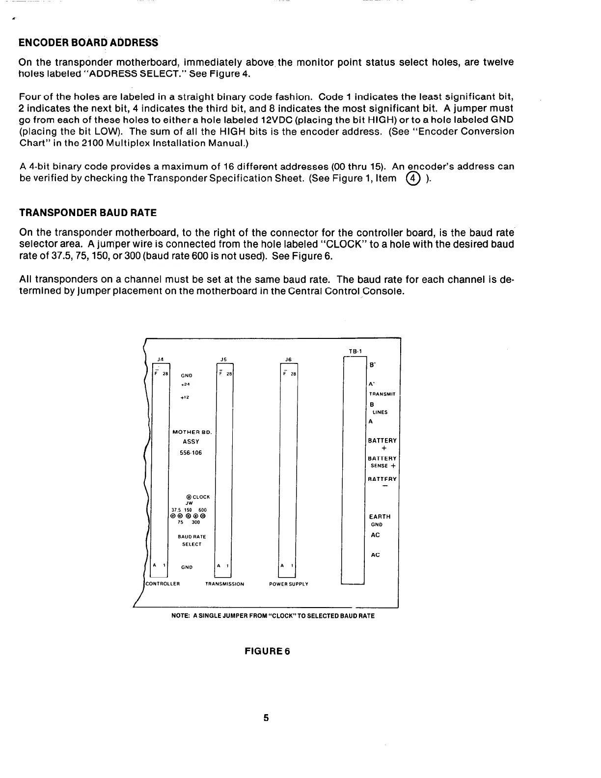
On the transponder motherboard, to the right of the connector for the controller board, is the baud rate
selector area. A jumper wire is connected from the hole labeled “CLOCK” to a hole with the desired baud
rate of 37.5,75,150, or 300 (baud rate 600 is not used). See Figure 6.
All transponders on a channel must be set at the same baud rate. The baud rate for each channel is de-
termined by jumper placement on the motherboard in the Central Control Console.
J6
-
I
-
16.1
--
8’
BATTER’
+
BATTER’
SENSE -I
BATTER’
EARTH
DND
AC
AC
NOTE: A SINGLE JUMPER FROM “CLOCK”T0 SELECTED BAUD RATE
FIGURE 6
5