8 S4007-0002-6 11/2015
16" (406 mm)
20-7/8" (530 mm)
20-3/16"
(512 mm)
2
3
4 5
1
6
7
9
21-1/8" (537 mm)
20-7/16"
(519 mm)
4-7/16" Deep (112 mm)
Exposed box for semi-flush mounting
1-3/4" (44 mm) minimum
Side View Reference
8
10
11
Finished wall surface (including
semi-flush Trim Kit if used)
3
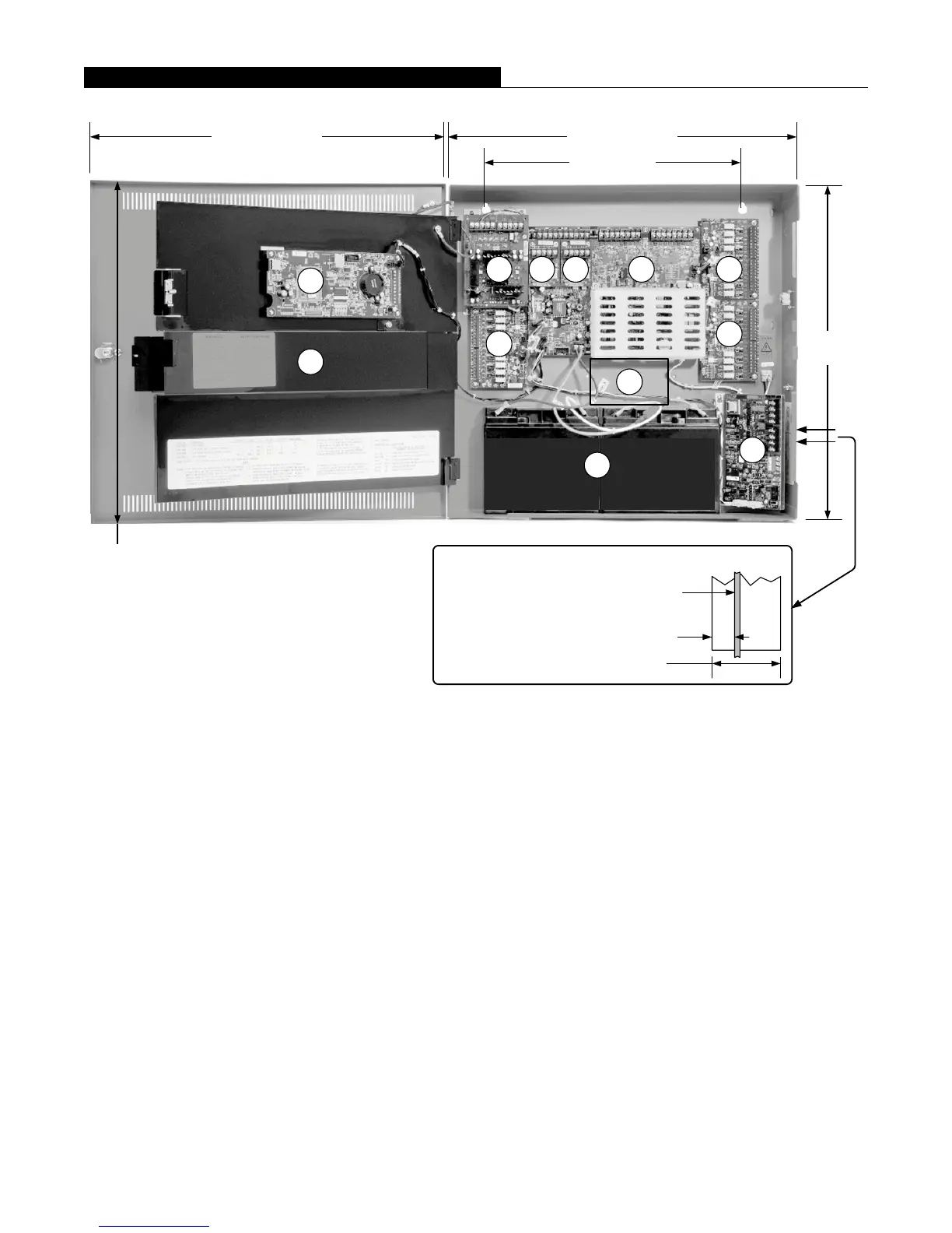
Module Locations:
1. Primary location for 4007-9801 Zone/Relay Module, or 4190-6106 TrueInsight Remote Service Gateway.
2. Location for a 4007-9802, 25 V Regulator Module (shown), a 4007-9804 IDNAC Dual Class A Isolator, or
an additional 4007-9801 Zone/Relay Module.
3. 4007-9803 IDNet+ Loop Expansion Modules, maximum of two (two are shown).
4. IDNAC Power Supply Assembly.
5. Location for additional 4007-9801 Zone/Relay Module.
6. Location for additional 4007-9801 Zone/Relay Module.
7. 4007-9807 or 4007-9808 City Circuit Module, or 4007-9809 Relay Module.
8. Battery location for up to 18 Ah batteries. Note: No conduit entry or wiring in this area, 14-7/8” (378 mm)
wide.
9. 4007-9806 SDACT location.
10. CPU and User Interface assembly.
11. Location for optional 4007-9805 LED Module.
NOTE: A system ground must be provided for Earth Detection and transient protection devices. This connection shall be
made to an approved, dedicated Earth connection per NFPA 70, Article 250, and NFPA 780.
4007ES Mounting and Module Location Reference