6
Expansion Power Supply (EPS) Installation Instructions
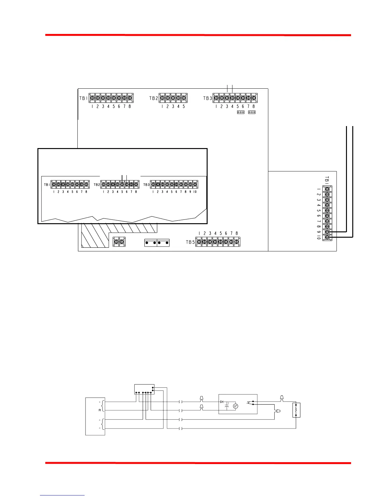
Auxiliary 24 V wiring
Figure 6 2098-9735 End-Of-Line Relay
Figure 5 Aux 24 V Wiring
• Aux terminals accept 18 AWG to 12 AWG wire.
• Conductors must test free of all grounds and stray voltages before connection to appliances, devices, and panel.
• All wiring is supervised and Power Limited.
• Voltage rating (24 VDC special application): 1 V p-p ripple (maximum)
0.5 A maximum available aux 24 V from EPS
Additional 0.5 A maximum available from Main System Board (MSB) aux 24 V
3 A total available from MSB NACs and MSB aux 24 V.
3 A total available from EPS NACs and EPS aux 24 V.
• Compatible with Simplex 4098 Series Peripherals; 2098 Series Relay Modules; all Simplex 4090 Series IDNet
Peripherals; and 4610-9111 / 4606-9101 Annunciators.
• If wiring is routed outside the building, use of a listed secondary protector is required. Use 2081-9044or 2081-9028. A
protector must be installed at each building exit/entrance. Each 2081-9044 adds 6 Ohms resistance at 200 mA. Each
2081-9028 adds 0.2 Ohms wiring resistance, and is rated for more than the 0.5 A aux 24 V capacity.
• If the circuit is used to power the Model 4098-9682 Four-Wire Base, the auxiliary 24 V power must be routed through the
2098-9735 End-Of-Line Relay, as shown in Figure 6 (below).
AUX 24 V
0.5 A MAX.
EXPANSION
POWER
SUPPLY
- +
AUX 24 V 0.5 A MAX
FROM MSB
- +
+ -
AUX 24 V 0.5 A MAX
FROM MSB
4008
MAIN SYSTEM BOARD
4006
MAIN SYSTEM
BOARD
LISTED
CONTROL
PA NE L
END-OF-LINE DEVICE
SELECTED PER ZONE
CIRCUIT
(RELAY SHOWN
ENERGIZED)
YELLOW
YELLOW
2098-9735
TYPICAL 4-WIRE ZONE 24VDC DEVICES
TYPICAL 4-WIRE
DETECTOR
24VDC
RED
BLACK
E.O.L. RELAY
24VDC
Power
IDC
Technical Manuals Online! - http://www.tech-man.com