3
The 4010-9814 and -9824 Suppression Release Kits install in their own
hardware slot located to the right of the 4010 SFI/O module (see Figure 2). Use
Steps 1 through 3 to mount the suppression release kit.
1. Disconnect battery and then AC power from the FACP.
2. With TB1 of the suppression release kit in the bottom position, slip the top
hole of the suppression release kit’s metal bracket over the flanges located
on the 4010 chassis.
3. Use the supplied slotted TORX screws (Part No. 441-002) and lock washers
to secure the other end of the suppression release kit’s bracket to the chassis.
4010-9813
Expansion Power
Supply (565-792)
or
4010-9814
Supression Power
Supply (565-793)
4010-9809
City Module
4010-9820
Meter Module
or
4010-9825
24V Extender
Terminal Block
4010-9806
Class A
Module
(565-789)
Pot for LCD Adjustment
4010-9806
Class A
Module
(565-789)
WARNING: PTCs MUST NOT TOUCH EACH OTHER OR
ANY OTHER METAL SURFACE!
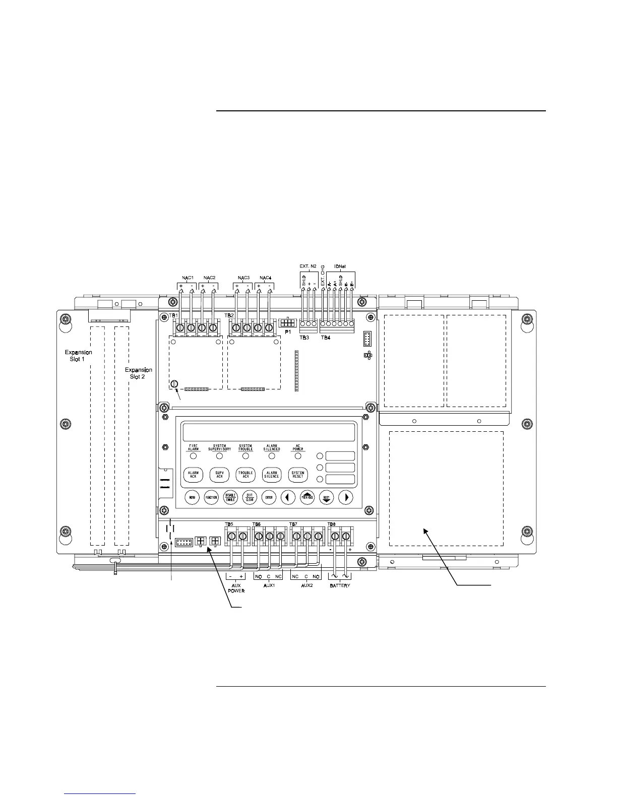
Figure 2. 4010 Suppression Release Kit
Continued on next page
Installation
Mounting
Expansion Supply
P13 (Red) and P14
(White) Expansion
Supply Connectors
Technical Manuals Online! - http://www.tech-man.com