12
INITIATING
DEVICE
CIRCUIT
BACKUP 2
PRIMARY 1
SEE NOTES 2, 3
4098-9685
2-WIRE DUCT DETECTOR
1
TB1
2 3 4 5 6 7 8
+Z
IN OUT
LED
+-
RELAY
+-
TEST-Z
9 10
4098-9834
REMOTE ALARM
INDICATOR /
KEYSWITCH
4098-9830
REMOTE INDICATOR
RED
ALARM
LED
SEE
NOTES
4, 5
BLK
RED
OPTIONAL
(SEE ACCESSORIES)
4098-9685
2-WIRE DUCT DETECTOR
1
TB1
2 3 4 5 6 7 8
+Z
IN OUT
LED
+-
RELAY
+-
TEST-Z
9 10
OPTIONAL
(SEE ACCESSORIES)
RED
ALARM
LED
TEST
SEE NOTES 4,5
EOL RESISTOR
(IF USED)
SEE NOTE 1
REDBLK
+
-
+
-
UL-LISTED
CONTROL PANEL
SIMPLEX 2120,
4001, 4002, 4004, 4005,
4020, 4100+ OR 4120
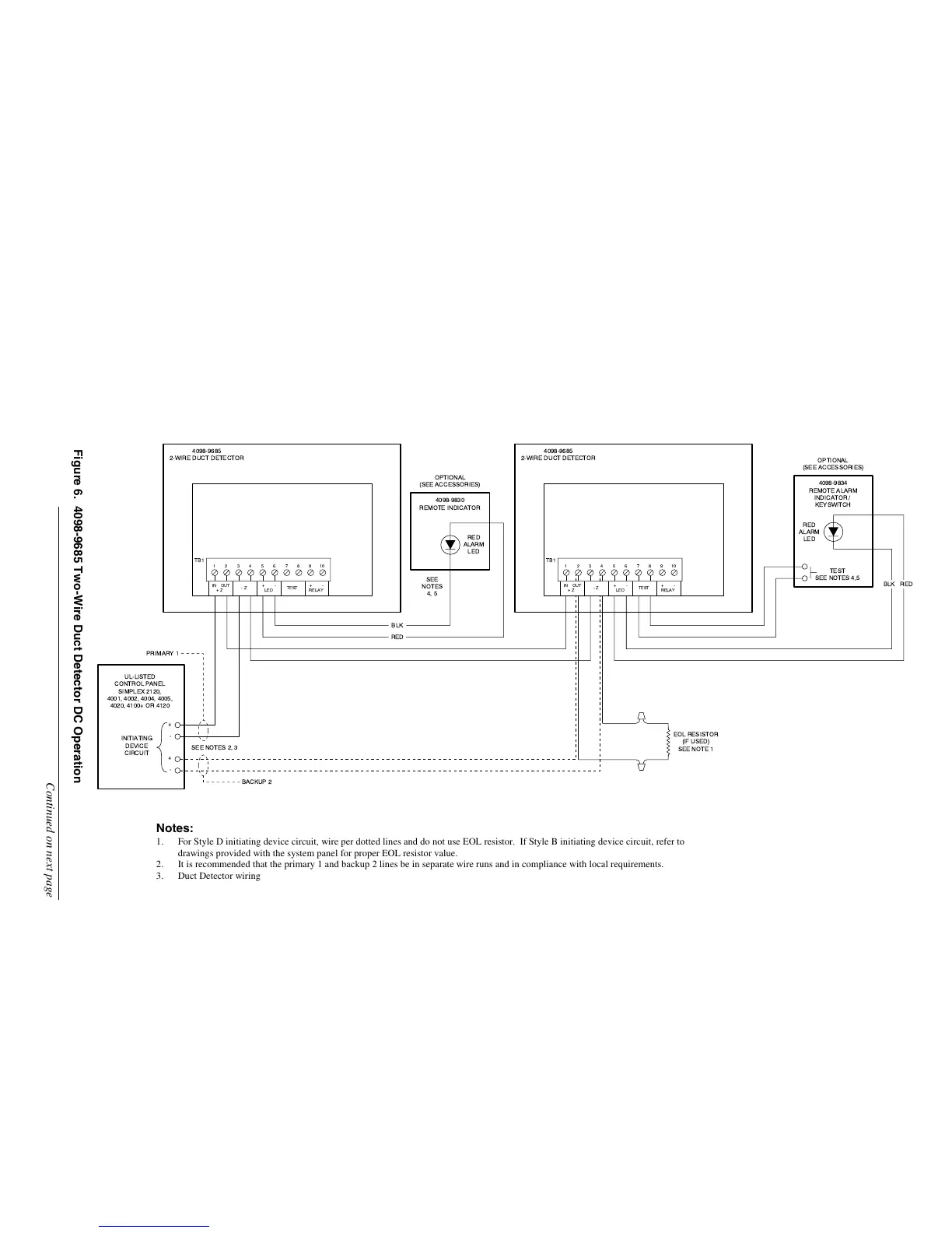
Figure 6. 4098-9685 Two-Wire Duct Detector DC Operation
Continued on next page
Notes:
1. For Style D initiating device circuit, wire per dotted lines and do not use EOL resistor. If Style B initiating device circuit, refer to
drawings provided with the system panel for proper EOL resistor value.
2. It is recommended that the primary 1 and backup 2 lines be in separate wire runs and in compliance with local requirements.
3. Duct Detector wiring is 12 to 18 AWG. For additional wiring information, refer to wiring diagrams supplied with the system panel.
4. The 4098-9834 and 4098-9830 are polarized; observe color coded wiring.
5. Maximum wire length to test terminals and remote LED is 250 feet.
Technical Manuals Online! - http://www.tech-man.com