19
If conduit is required, route conduit to the most convenient knockout and secure
to the assembly using suitable fittings.
Note: The unused conduit entry is sealed off using the cap plug (included with
ship group 748-518). Apply even pressure on the plastic cap plug to
secure it against the conduit plate. The cap plug seals and removes
easily with moderate pressure.
Connect wires to the appropriate terminals within the duct housing in accordance
with the system wiring diagram and the appropriate typical installation diagram.
Perform all wiring in accordance with the requirements of the National Electric
Code
and local codes.
Connect the optional accessory as specified in the following paragraph and the
associated installation and wiring diagrams.
Note: Only one remote indicator may be connected to each 4098-9685, 4098-9686,
4098-9688, 4098-9755, or 4098-9756.
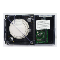
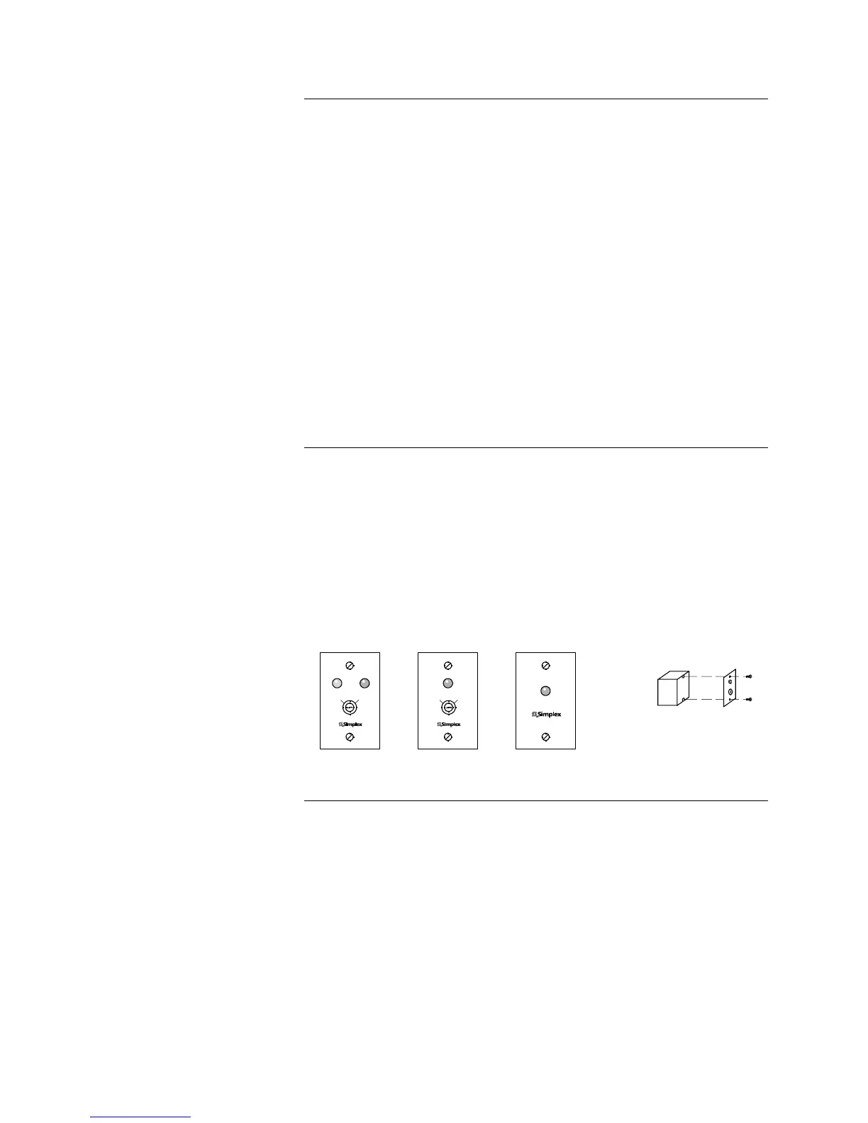
The 2098-9806, 2098-9808, 4098-9830, 4098-9834, and 4098-9835 accessories
are intended for installation to a standard 2-inch x 3-inch outlet box having a
depth of at least two inches. See Figure 15 for details. Make wiring connections
in accordance with the installation wiring diagram prior to attaching accessory to
the box.
Note: Maximum wire length to test terminals and remote LED is 250 feet.
4098-9830
OR
2098-9808
ALARM INDICATOR
ALARM
4098-9834
OR
2098-9806
ALARM INDICATOR/
KEY SWITCH
ALARM
LISTED STEEL
DEVICE BOX
(BY OTHERS)
ACCESSORY
ACTUAL ACCESSORY MAY VARY
SLIGHTLY FROM PICTURE SHOWN
4098-9835
ALARM/POWER
INDICATOR/KEY SWITCH
ALARM
TEST
NORMAL
POWER
TEST
NORMAL
Figure 15. Accessory Installation
Continued on next page
Installation, Continued
Wiring Procedures
Accessory Installation
Technical Manuals Online! - http://www.tech-man.com