3
The procedures that follow are used to install the 4098-9755 or 4098-9756
addressable duct sensors. See Figure 1 for the location of the duct sensor DIP
switches. The instructions provided show how to set the address at each sensor
and also how to make electrical connections. Addressable smoke duct sensors are
connected to a 2120 Multiplex Communicating Device Transponder (CDT), 4010
Fire Alarm Panel, 4020 Fire Alarm Panel, 4100+ Fire Alarm Panel, or 4120 Fire
Alarm Panel by a single twisted-shielded wire pair (MAPNET II/IDNet).
Duct sensor addressing is critical since the 2120 Communicating Device
Transponder (CDT), 4010, 4020, 4100+, and 4120 Systems report alarms and
troubles per duct sensor rather than per zone. Each duct sensor has a unique
address. This address is associated with a custom label which identifies its
physical location within a building. The duct sensor’s address and location must
match up with the address listed in the specification sheets of the 2120 Job
Configuration Report or Programmer’s Report for the 4010, 4020, 4100+, or
4120 System. You should have the appropriate specification sheets with you
during this part of the installation.
1. Using the 2120 Job Configuration Report, find the entry for the duct sensor
you are about to install. The CUSTOM LABEL column provides the
location while the DEVICE ADDRESS column provides the switch setting
data.
2. Using the switch setting data for the duct sensor you are installing set the
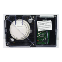
duct sensor’s address using Figure 3. Loosen the four screws securing the
clear plastic cover to the housing base. Locate the DIP switch on the duct
sensor’s PCB assembly in the wiring compartment (see Figure 1). Use a
small screwdriver or pen to set the switches.
For the switch setting data in the DEVICE ADDRESS column, “1” is switch
ON while “0” is switch OFF.
3. Recheck the location of the sensor and its address before electrical
installation. Mark an address label with the appropriate address for your
duct sensor by shading a label box for each sensor DIP switch in the ON
position. Then apply the label to the sensor near the sensor’s DIP switches.
4. Secure the duct sensor’s clear plastic cover to the housing using the four
screws (Torque screw to 8-10 inch-pounds).
1. Using the System Point Summary for the 4010, 4020, 4100+, or 4120, find
the entry for the duct sensor you are about to install. The ZONE NAME
(with a “M” prefix) and CUSTOM LABEL are located in the SYSTEM
POINT SUMMARY.
For example, Address M1-7 (for the 4010, 4100+, or 4120 System) is
shaded in Figure 2. M1 is the addressable channel while -7 is the device
address on the channel. For a duct sensor with Address M1-7, address 7
must be set on the duct sensor’s DIP switches. Address 7 is illustrated in
Figure 3.
Continued on next page
Setting the Duct Sensor’s Address
Addressable Duct Sensors
4098-9755 or 4098-9756
(MAPNET II/IDNet)
General
Address Setting for the 2120
CDT System (use with
4098-9755 only)
Address Setting for the 4010,
4020, 4100+, or 4120
Technical Manuals Online! - http://www.tech-man.com