11
Accessory installation instructions are provided on Page 19 of this publication.
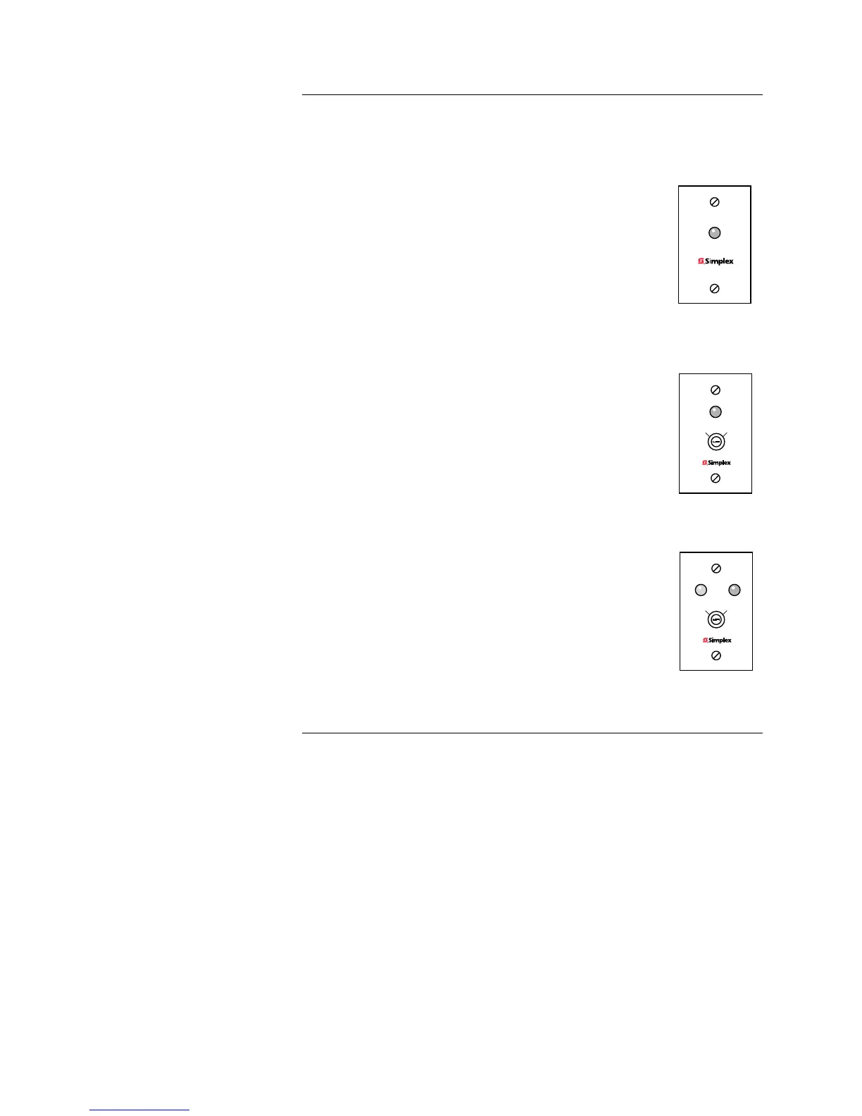
Remote Alarm Indicator - Model 2098-9808 (Use with 4098-9755 or
4098-9756) or Model 4098-9830 (Use with 4098-9685, 4098-9688, or
4098-9686)
• Red LED indicator ON when detector/sensor is in alarm
• LED Alarm Current - 1.2mA Nominal
Remote Alarm Indicator/Key Switch - Model 2098-9806 (Use with
4098-9755 or 4098-9756) or Model 4098-9834 (Use with 4098-9685,
4098-9688, or 4098-9686)
• Red LED indicator ON when detector/sensor is in
alarm. Key switch activates alarm relay 4098-9756,
4098-9688, or 4098-9686 only), remote LED, and puts
the detector/sensor into alarm
• LED Alarm Current - 1.2mA Nominal
Remote Power/Alarm Indicator/Key Switch - Model 4098-9835 (Use
with four-wire 4098-9686)
• Green LED indicator glows with power ON
• Red LED indicator ON when detector is in alarm
• Key Switch activates alarm relay, remote LED, and
puts the detector into alarm
• Standby Current - 20mA (green LED) at
24VDC Nominal
• LED Alarm Current - 1.2mA (red LED) Nominal
Note:
Maximum wire length to test terminals and remote LED is 250 feet.
Continued on next page
Electrical Specifications, Continued
Accessories
ALARM
ALARM
TEST
NORMAL
POWER
ALARM
TEST
NORMAL
Technical Manuals Online! - http://www.tech-man.com